Compact seating arrangement

a seating arrangement and compact technology, applied in the field of compact seating arrangement, can solve the problems of compromising the ergonomics of the driver in compact vehicles, and achieve the effect of widening the trunk or body and increasing the width

Active Publication Date: 2012-09-18
GORDON MURRAY DESIGN LTD
View PDF10 Cites 15 Cited by
  • Summary
  • Abstract
  • Description
  • Claims
  • Application Information

AI Technical Summary

Benefits of technology

[0009]In either case, the arrangements of the seats is such that advantage can be taken of the fact that the human passenger generally has a wider trunk or body than legs, and specifically has shoulders of greater width than the width of the legs. This enables passengers to be comfortably seated on the respective rear seats with the front driver's seat overlapping the legs of the passengers. This overlapping arrangement enables the cabin of a vehicle to be kept relatively narrow and yet provide accommodation for the driver and for at least two passengers sat side by side.

Problems solved by technology

A variety of seating arrangements comprising a central driver's seat and two rear passenger seats have previously been proposed but these have tended to suffer from various practical limitations or inconveniences so have not been widely adopted.
Compact vehicles tend to suffer from compromised driver ergonomics because the front wheel arch intrudes into the passenger cabin.

Method used


Image

  • Compact seating arrangement
  • Compact seating arrangement
  • Compact seating arrangement

Examples


first embodiment

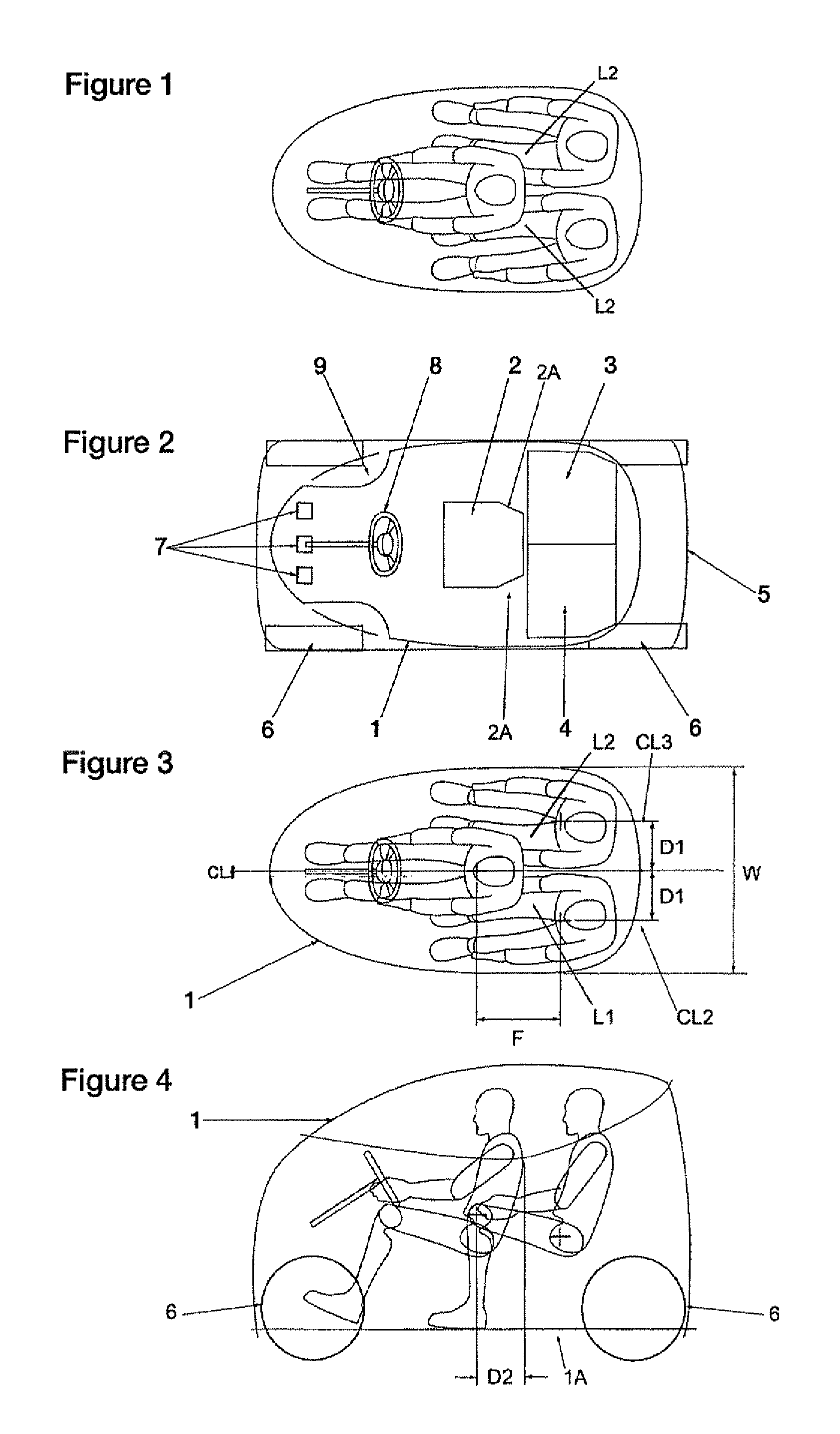
[0026]FIGS. 1 to 3 show schematic plan views of a cabin 1 of a vehicle, showing a compact seating arrangement therein. As will be seen, there is a single, centrally arranged driver's seat 2 and two rear passenger seats 3 and 4 which are aligned substantially transversely. Although the driver's seat 2 is arranged generally in front of the two rear passenger seats, the driver's seat 2 extends transversely to overlap part of each rear passenger legs L1, L2. The driver's seat is shaped at 2A to provide accommodation for at least a part of the inboard leg of each passenger (as shown in FIGS. 1 and 3). The three seat arrangement shown in FIGS. 1 to 3 is comfortable and provides easy access to the seats 2, 3 and 4 for all of their occupants. The seating arrangement is such as to keep the overall width and length taken up by the seats 2, 3 and 4 as small as possible. This compact arrangement is achieved, whilst also providing the necessary space and comfort for the occupants, by utilising t...

second embodiment

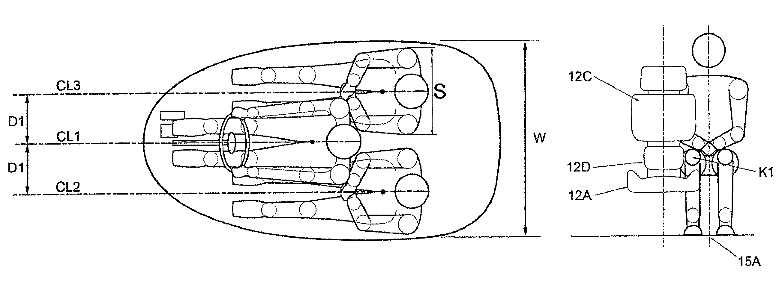
[0034]FIGS. 8-15 illustrate a seating arrangement according to the invention. This is similar to the arrangement shown in FIGS. 1-7 but with some small changes in the various dimensions of the layout. FIGS. 8-15 also show features of the seats and the positions of the occupants therein in a little more detail. FIG. 8 shows a plan view of a vehicle incorporating this seating arrangement and shows a cabin 11, a driver's seat 12, two rear passenger seats 13, 14, the body 15 of the vehicle, its wheels 16, control pedals 17, a steering wheel 18 and front wheel arches 19.

[0035]As shown in FIG. 8, the driver's seat comprises a seat base 12A, a seat back 12B and a headrest 12C. Rearward portions of the seat base 12A, on each side thereof, are shaped, e.g. by the provision of a cut-out 12D to provide a space to accommodate at least part of a leg of a passenger seated in a rear passenger seat. By this means, the seat base 12A enables the rear seats 13, 14 (and the inboard leg of a passenger s...


PUM


Abstract

A compact seating arrangement for a vehicle, the seating arrangement comprising three seats: a front driver's seat arranged centrally and, at least to some extent, forward of two transversely aligned rear passenger seats, wherein the driver's seat extends transversely so as to be positioned in front of part of each of the rear passengers' seats, the extent of the overlap in the transverse position of the driver's seat and the rear passenger seats being such that each side of the driver's seat is required to be shaped so as to be able to accommodate at least part of a leg of a passenger seated in a forward facing position in a respective one of the passenger seats.

Description

CROSS-REFERENCE TO RELATED APPLICATION[0001]This Application is a Section 371 National Stage Application of International Application No. PCT / EP2008 / 000892, filed Mar. 14, 2008 and published as WO 2008 / 110814 A2 on Sep. 18, 2008, the content of which is hereby incorporated by reference in its entirety.FIELD OF THE INVENTION[0002]This invention relates to a compact seating arrangement for a vehicle, in particular comprising a central driving seat and two rear passenger seats aligned substantially transversely.BACKGROUND OF THE INVENTION[0003]A variety of seating arrangements comprising a central driver's seat and two rear passenger seats have previously been proposed but these have tended to suffer from various practical limitations or inconveniences so have not been widely adopted. In more recent years, such a seating arrangement for a sports car has been described in WO9218347 by the inventor of the present case and the seating arrangement used in the McLaren F1 (trade mark) sports...

Claims


Application Information

Patent Timeline
Patent Type & Authority Patents(United States)
IPC IPC(8): B60N2/01B60N2/90
CPCB60N2/36B60N2/01B62D31/003
Inventor MURRAY, IAN GORDON
Owner GORDON MURRAY DESIGN LTD
Why Eureka
Try Eureka