Optical comparator with digital gage

a digital gage and comparator technology, applied in the field of optical metrology, can solve the problems of difficult to make fine comparisons to customary certainty, limit the precision with which comparisons can be made for given, and high cost of plate manufacturing to required accuracy, so as to preserve reliability and robustness, easy to discern the effect of indication

Active Publication Date: 2012-09-18
QUALITY VISION INT
View PDF37 Cites 5 Cited by
  • Summary
  • Abstract
  • Description
  • Claims
  • Application Information

AI Technical Summary

Benefits of technology

[0005]The invention among its preferred embodiments digitally generates templates for optical projection onto the viewing screens of optical comparators concurrently with the optical projection of images of test parts onto the same viewing screens. The accuracy with which the images of the test parts are projected onto the viewing screens is largely a function of the illuminating and projection optics and is not constrained by any intervening digital pixilation of test part images. Although optically projected onto the same viewing screens, the templates are digitally generated having regard to the projected pixel size on the viewing screens. As such, the invention preserves the reliability and robustness long associated with optical comparators while obviating the need for physical templates. The combined optical projections of the test part and the digitally generated template also allow for overlapping color based comparisons for providing more easily discernable indications as to whether test parts are within tolerance.
[0009]The interface between the digital CAD files and the digital display engine of the video projector can produce template structures to compensate for resolution limitations of the pixilated template pattern at a given magnification for making sub-pixel comparisons with the projected image of the test part. For example, the location of a boundary line can be more precisely represented by laterally staggered sets of pixels in the pixilated template pattern. A nominal line, which represents the intended boundary, is implicit from the staggered sets of pixels as a line that can be adjudged on the viewing screen to exactly bisect the staggered sets of pixels. The laterally staggered sets of pixels can also be laterally separated by an amount that straddles an intended tolerance zone. The projected image of the test part contains edges whose resolution is not limited by a pixel count and can divide the individual staggered sets of pixels appearing on the viewing screen into different size areas of fractional pixel dimensions that can be compared for a more precise determination of the locations of the edges with respect to the boundary or tolerance zones at a resolution higher than the resolution of the pixels representing the boundary or tolerance zones. Such multi-pixel boundary enhancements can also be used in combination with additive color controls for more easily distinguishing areas of overlap between the boundaries or tolerance zones projected in one color and the image of the test part projected in another color.
[0010]Preferably, the optics for projecting the image of the pixilated template pattern onto the viewing screen are sufficiently independent of the optics for projecting the image of the test part onto the viewing screen so that a change in the magnification of the image of the test part does not affect the number of pixels available for imaging the rescaled pixilated template pattern projected onto the viewing screen. The digital display engine of the video projector can magnify the template pattern by generating a digital image of a smaller portion of the template pattern using the same number of pixels, which are projected at the same optical magnification onto the viewing screen. Since a smaller portion of the template pattern is generated by the same number of available pixels, the resolution of the so-magnified template pattern as projected upon the viewing screen is increased. In other words, the same visible spacing between pixels on the viewing screen represents a smaller distance according to the scale of the increased magnification.
[0011]The optical projector can project the image of the test part to the viewing screen along a first optical axis, and the video projector can project the image of the pixilated template pattern to the viewing screen along a second optical axis that is inclined to the first optical axis. An optic, such as a segmented lens (e.g., Fresnel lens) or grating, can be overlaid on the viewing screen to combine light energies of the projected images approaching the viewing screen along the first and second optical axes into light energies emanating from the viewing screen along a common viewing axis. The alignment of light energies between the images produced by the optical and video projectors provides for more uniform comparisons of color and contrast throughout the viewing screen.

Problems solved by technology

The templates can be expensive to manufacture to required accuracy and can require special storage and handling provisions to preserve the templates in working condition.
However, the computer monitors present pixilated images that significantly limit the precision with which the comparisons can be made for given size images appearing on the computer screen.
Thus, fine comparisons can be difficult to make to customary certainty and can require visual inspection of smaller segments of the test parts within the same size field of view.
The digital conversion of the test part images contributes additional systematic and random errors that reduce the reliability of the measurements as well as the perceived robustness previously derived from comparing actual images of test parts against reference datum.

Method used


Image

  • Optical comparator with digital gage
  • Optical comparator with digital gage
  • Optical comparator with digital gage

Examples


Embodiment Construction

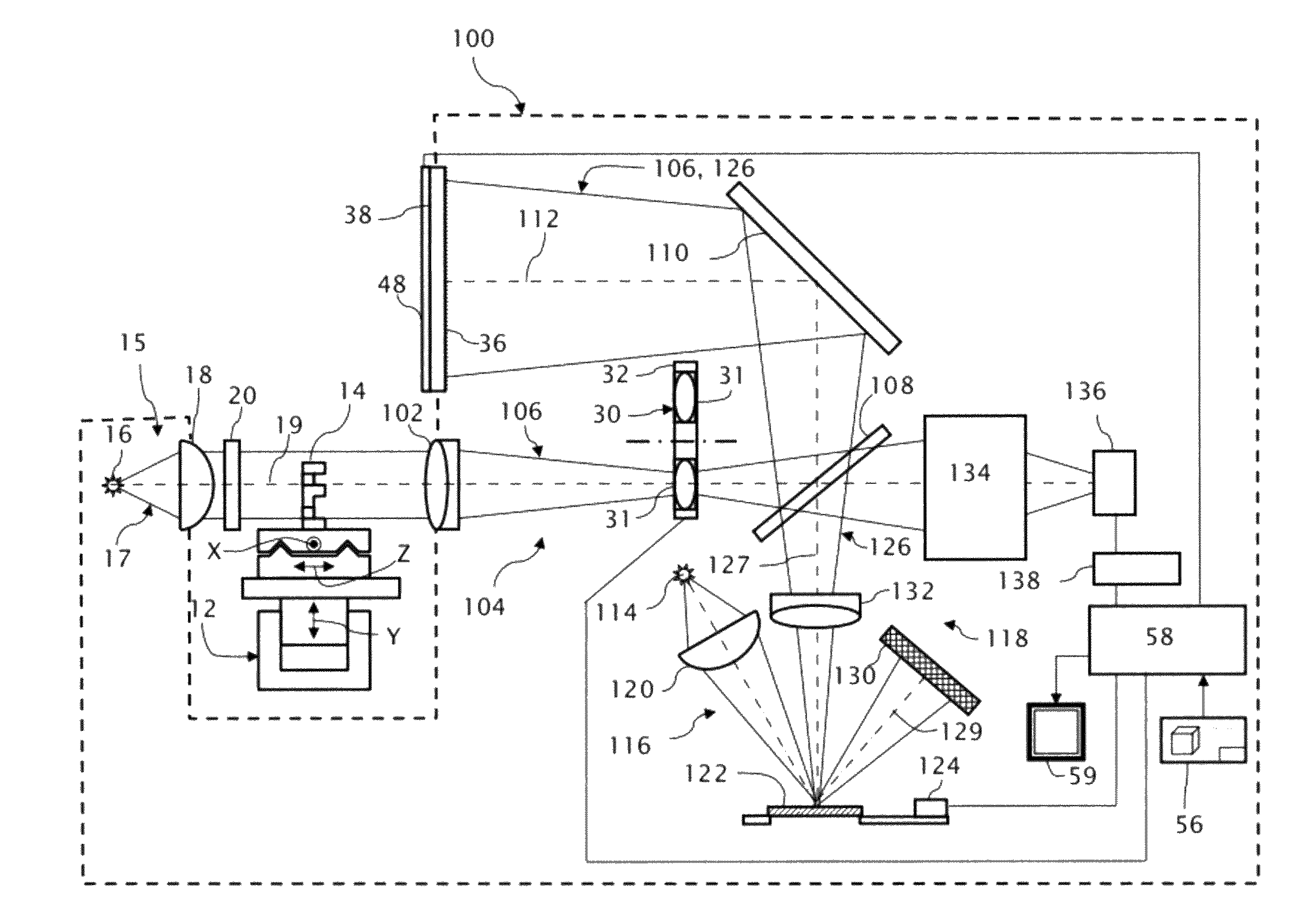
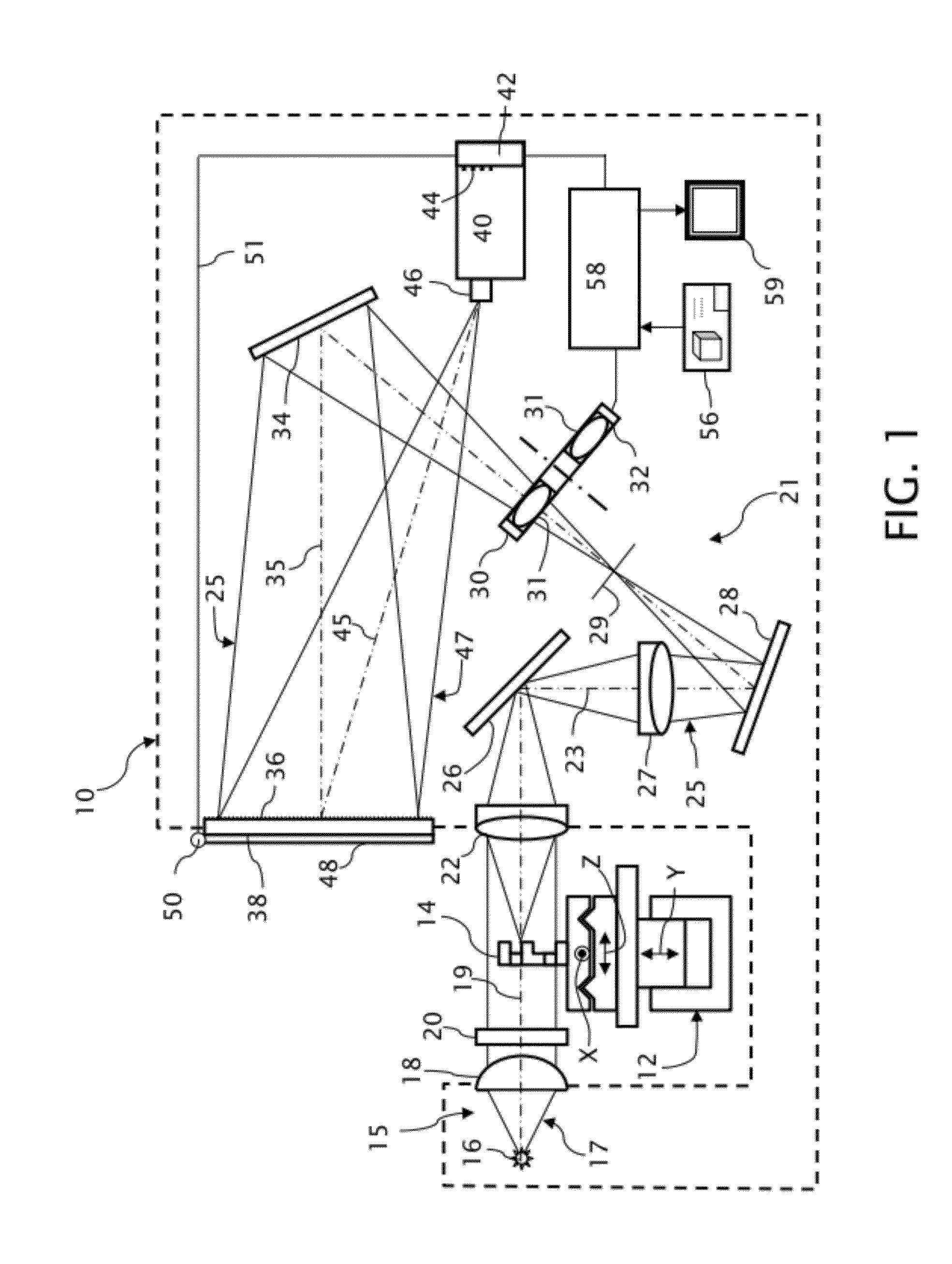
[0024]An optical comparator 10, whose outline is depicted by dashed lines in FIG. 1, includes a multi-axis stage 12 for supporting a test part 14. The multi-axis stage 12 is depicted as having three orthogonal axes X, Y, and Z of translation (i.e., linear motion) but could include fewer axes of translation or one or more additional axes of rotation (i.e., angular motion), also preferably orthogonal. Various manual controls (not shown) can be associated with the multi-axis stage 12 to adjust the position of the test part 14, which can also include motors, actuators, or the like for automatically positioning and / or moving the test part 14 under inspection. In addition, at least the linear motion axes X and Y are preferably equipped with graduated linear encoders (not shown) for measuring the changes in the position of the test part 14.

[0025]A backlight (profile) illuminator 15 outputs an illumination beam 17. Included within the illustrated backlight illuminator 15 is a light source 1...


PUM


Abstract

An optical comparator arranged for rear projection onto a viewing screen combines an optical projector that projects an optical image of a test part under inspection onto the viewing screen with a video projector that projects an optical image of a pixilated template pattern containing illustrated specifications of the test part onto the same viewing screen. The images of the test part and the pixilated template pattern are projected concurrently onto the viewing screen for visually comparing the form of the test part against its specified form.

Description

TECHNICAL FIELD[0001]The invention relates to the field of optical metrology and particularly to the gaging of test parts through optical imaging systems that provide for comparing the test parts against templates or other representations of the test parts.BACKGROUND OF THE INVENTION[0002]Optical comparators, particularly of a type that project a shadow image (e.g., a negative image) or an obliquely illuminated image of a test part onto a screen overlaid by a template of the test part, have enjoyed widespread acceptance as robust and reliable forms of measurement by providing measurement results in a visually verifiable form. Differences between projected edge features of the test part and one or more tolerance boundaries of the same features inscribed on the templates are readily apparent on the comparator screens. While numerical data can also be extracted by monitoring motions of the test parts against calibrated images of the test parts appearing on the comparator screens, the n...

Claims


Application Information

Patent Timeline
Patent Type & Authority Patents(United States)
IPC IPC(8): G01B9/08
CPCG03B21/14G01B9/08G03B21/10G03B21/28G03B43/00
Inventor POLIDOR, EDWARD T.GELMAN, BORIS
Owner QUALITY VISION INT
Why Eureka
Try Eureka