Dynamic focusing and tracking for wireless power transfer arrays

a wireless power transfer array and dynamic focus technology, applied in the field of wireless power transfer, can solve the problems of small variations in the received power at the charging device, significant reduction in the dynamic range and accuracy of received power measurement, and further hampered fine tuning of the phase, so as to achieve a significantly shorter convergence time, higher receive power, and high dynamic range

Active Publication Date: 2020-12-29
GURU WIRELESS INC
View PDF22 Cites 1 Cited by
  • Summary
  • Abstract
  • Description
  • Claims
  • Application Information

AI Technical Summary

Benefits of technology

[0009]Wireless power transfer systems in accordance with many embodiments of the invention operate reliably in noisy and interference-prone environments due to the higher dynamic range and multi-layer adaptive natures. They can also be highly suitable for multipath environments, which can be prominent in indoor and other terrestrial applications. Also due to its option to operate adaptively, convergence time can be significantly shorter, while producing significantly higher receive powers at the RU. The robustness and reliability of the approach to environmental and system nonidealities (for instance, coupling and pulling) can also be higher due to blending of the individual core values in the defined optimization basis masks. The disclosed invention has several aspects that can work in concert and are discussed below in no particular order.

Problems solved by technology

Although, there exists a combination of phases and / or amplitdues of the wireless power sources that results in maximum power at the charging device, finding such combination (i.e., optimization for a given location and orientation) is a challenging task in general.
This approach can result in small variations in the received power at the charging device, especially when a large array is involved, since the power fluctuations as the phase is swept can be due to interference between one element and the rest of the elements.
In practice, due to noise and interference, the error in the detected signal can be quite large and can result in a significant reduction in the dynamic range and accuracy of received power measurements.
Also, fine tuning of the phase can be further hampered by the yet smaller changes in the receiving device's power which can be almost entirely masked by noise and interference, resulting in errors.
Another challenge with such approaches is that in reality the coupling between the elements (sometimes referred to as phase pulling or simply pulling) can produce undesirable projections and imperfections even when the phases were individually and independently optimized.
Furthermore, the approach of varying the phase of elements one at a time does not scale well to larger arrays.
This makes searching through all possible combinations all but impossible.

Method used


Image

  • Dynamic focusing and tracking for wireless power transfer arrays
  • Dynamic focusing and tracking for wireless power transfer arrays
  • Dynamic focusing and tracking for wireless power transfer arrays

Examples


Embodiment Construction

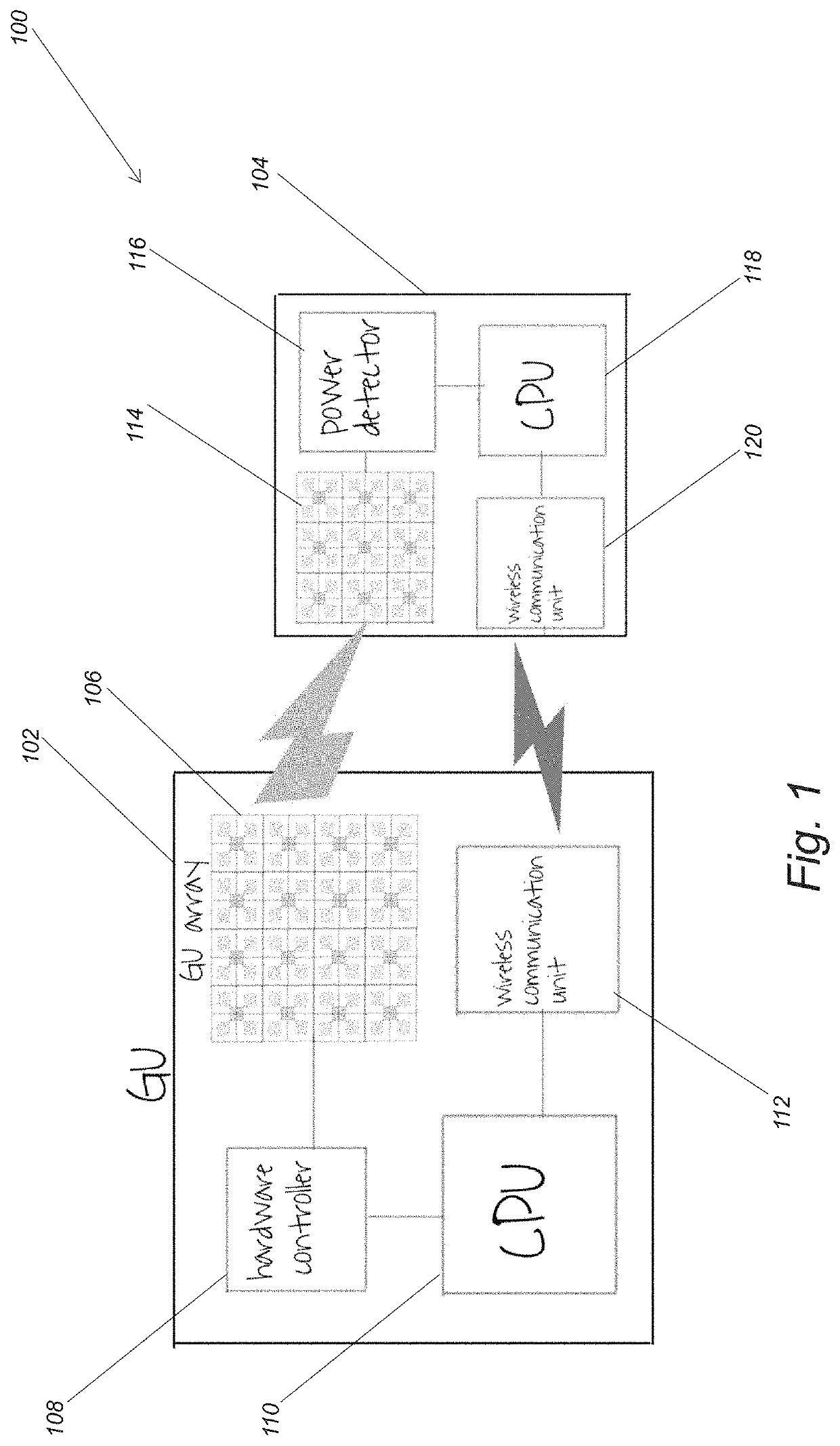
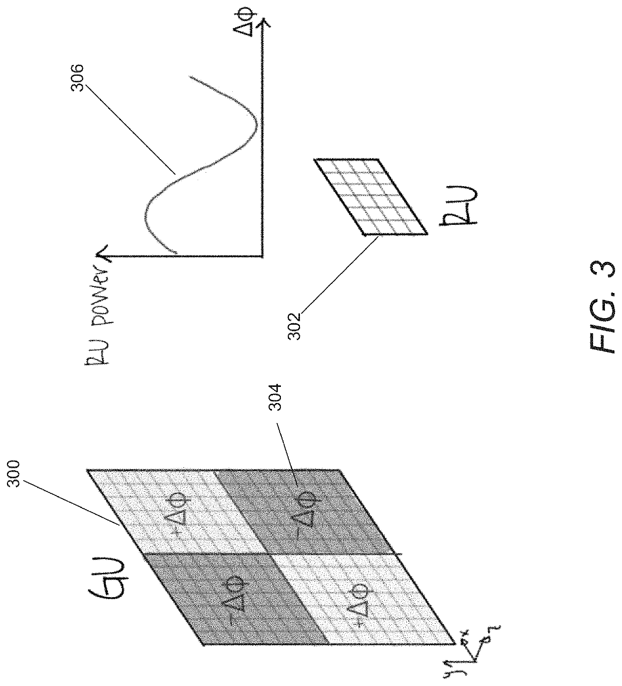
[0044]Turning now to the drawings, wireless power transfer systems and methods for focusing wireless power transfer arrays in accordance with various embodiments of the invention are illustrated. Wireless power transfer systems in accordance with various embodiments of the invention include one or more wireless power generation units (GU) that can include multiple synchronized RF power sources (RF sources) and antennas, in addition to various other functions such as (but not limited to) processing capability, hardware interfaces, and / or communication capabilities. In many embodiments, each GU includes circuitry that can adjust the phase of each transmitted RF source to allow constructive interference in a specific location or multiple locations in space where one or more recovery unit(s) (RU) is present. In certain embodiments, the GU can also adjust the amplitude of each transmitted RF source. In embodiments where the GU can adjust the amplitude in addition to the phase of the RF s...


PUM


Abstract

Wireless power transfer systems and methods for focusing wireless power transfer arrays are disclosed. One embodiment includes a wireless power generating unit (GU) including a processing system configured to focus the RF power sources by: sending control signals to the control circuitry to perform a plurality of sweeps using each of a plurality of different basis masks; receiving a message from a RU containing a report based upon received power measurements made by the RU; and sending control signals to focus the RF power sources based on the received message from the RU. Furthermore, each sweep includes performing a phase sweep across a phase sweep range at a plurality of phase step increments with respect to a first group of RF power sources identified in a basis mask, where the first group of RF power sources comprises a plurality of RF power sources.

Description

CROSS-REFERENCE TO RELATED APPLICATIONS[0001]The current application claims priority to U.S. Provisional Patent Application No. 62 / 781,514, entitled “Dynamic Focusing and Tracking for Wireless Power Transfer Arrays” and filed Dec. 18, 2018, the disclosure of which is incorporated herein by reference in its entirety.FIELD OF THE INVENTION[0002]The present invention relates generally to wireless power transfer and more specifically to non-proximity wireless power transmission using beamforming and focusing.BACKGROUND[0003]Non-proximity wireless power transmission at a distance through use of radio frequency (RF) and mm-wave beam forming and focusing can enable and / or enhance a plethora of new applications. For example, the proliferation of internet of things (loT) devices and sensors can be substantially accelerated by wirelessly delivering power to them and avoiding the need for extra wiring during installation of such devices. Another example of practical usage of such devices is co...

Claims


Application Information

Patent Timeline
Patent Type & Authority Patents(United States)
IPC IPC(8): H02J50/40H04W4/02H02J50/20H04W4/80H04B5/00
CPCH04B5/0037H02J50/40H04W4/025H02J50/20H04W4/80H02J50/80H02J50/402
Inventor HAJIMIRI, SEYED ALIABIRI, BEHROOZBOHN, FLORIANTEBBI, FARHUD
Owner GURU WIRELESS INC
Why Eureka
Try Eureka