Magnified-projection optical system and digital type planetarium device
a technology of magnification projection and optical system, applied in the field of projection optical system, can solve the problems of high performance and hence the inability to obtain clear projection image, and the tendency to increase the size of the illumination system, so as to reduce chromatic aberration, reduce the effect of chromatic aberration and small focal distan
- Summary
- Abstract
- Description
- Claims
- Application Information
AI Technical Summary
Benefits of technology
Problems solved by technology
Method used
Image
Examples
example
Example 1
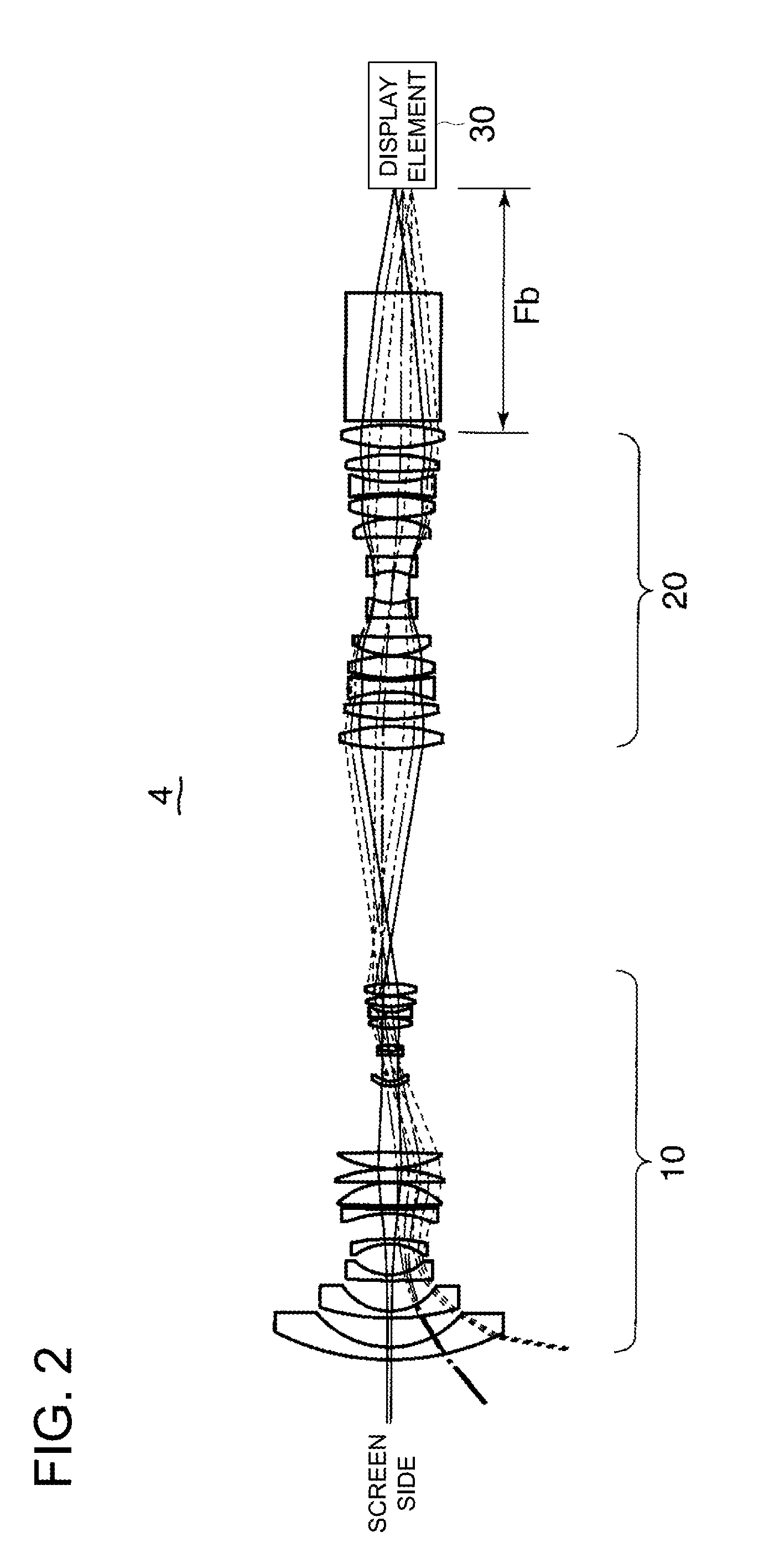
[0199]The following describes the first Example of the magnified-projection optical system of the present invention: The structure of the first Example is the same as those of FIGS. 2 through 4.
[0200]The following shows the construction data of each lens in the first Example:
[0201]
Numerical value of Example 1Unit: mmSurface dataSurface number:rdndvdScreen: 6250.0006250.001116.3366.001.5168064.20243.90213.953110.0393.341.6204160.34426.32214.455363.0382.601.6584450.85623.89114.507−26.7992.301.7440044.908−82.79212.059−52.6112.231.8051825.4610457.0991.6011554.59410.801.6034238.0112−35.4170.20132085.7846.151.6034238.0114−69.0000.201550.0307.601.5168064.2016−498.56031.301713.4442.301.7552027.531810.31110.4019(stop)∞1.8020−141.6341.861.7440044.902116.0112.831.5168064.2022−31.4258.022328.1645.001.4970081.6124−25.0920.2525−194.5582.401.8061040.732620.7032.602738.2074.901.4970081.6128−32.5630.402939.1165.501.4970081.6130−43.05319.2531(dummy)91.513290.37110.501.4970081.6133−77.9483.50...
example 2
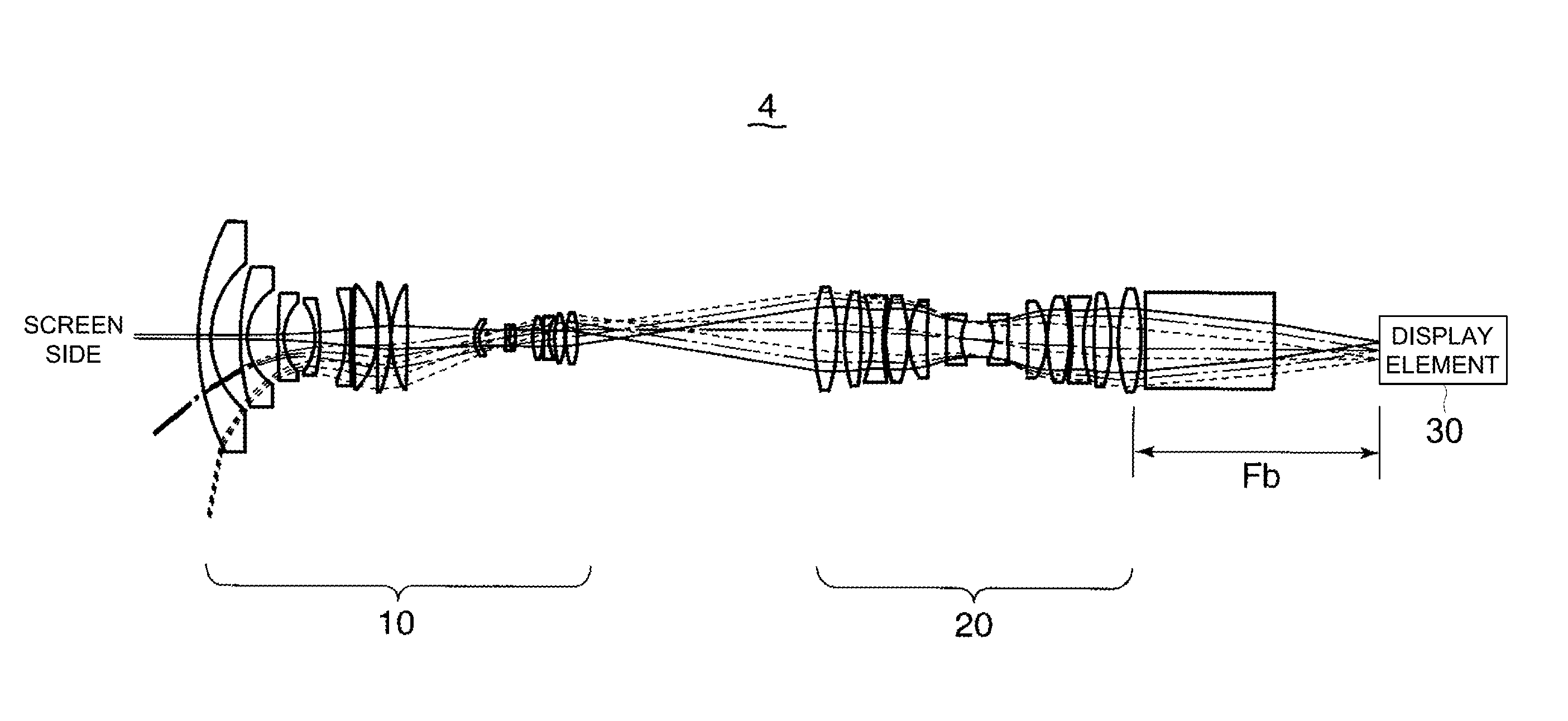
[0204]The following describes the magnified-projection optical system of the second Example. FIG. 7 overall schematic diagram representing the magnified-projection optical system. As shown in FIG. 7, the magnified-projection optical system 4 of the second Example includes a projection optical system 10, relay optical system 20 and display element 30 sequentially arranged along the optical axis K1 in that order as viewed from the screen 1, similarly to the case of FIG. 2.
[0205]FIG. 8 is the overall schematic diagram representing the projection optical system 10. FIG. 9 is the overall schematic diagram representing the relay optical system 20 in the second Example. As will be apparent from comparison with FIG. 4, in the relay optical system 20 of FIG. 9, the length of the prism PR1 in the direction of optical axis K1 is greater than that of FIG. 4.
[0206]The following describes the construction data of each lens in the second Example.
[0207]
Numerical value of Example 2Unit: mmSurface da...
PUM
 Abstract
Description
Claims
Application Information
 - R&D
- Intellectual Property
- Life Sciences
- Materials
- Tech Scout
- Unparalleled Data Quality
- Higher Quality Content
- 60% Fewer Hallucinations
Browse by: Latest US Patents, China's latest patents, Technical Efficacy Thesaurus, Application Domain, Technology Topic, Popular Technical Reports.
© 2025 PatSnap. All rights reserved.Legal|Privacy policy|Modern Slavery Act Transparency Statement|Sitemap|About US| Contact US: help@patsnap.com


