
Adjustable silencer booster with spoked piston engagement shoulder

Inactive Publication Date: 2012-09-25
JJE BRANDS LLC
View PDF5 Cites 35 Cited by
  • Summary
  • Abstract
  • Description
  • Claims
  • Application Information

AI Technical Summary

Benefits of technology

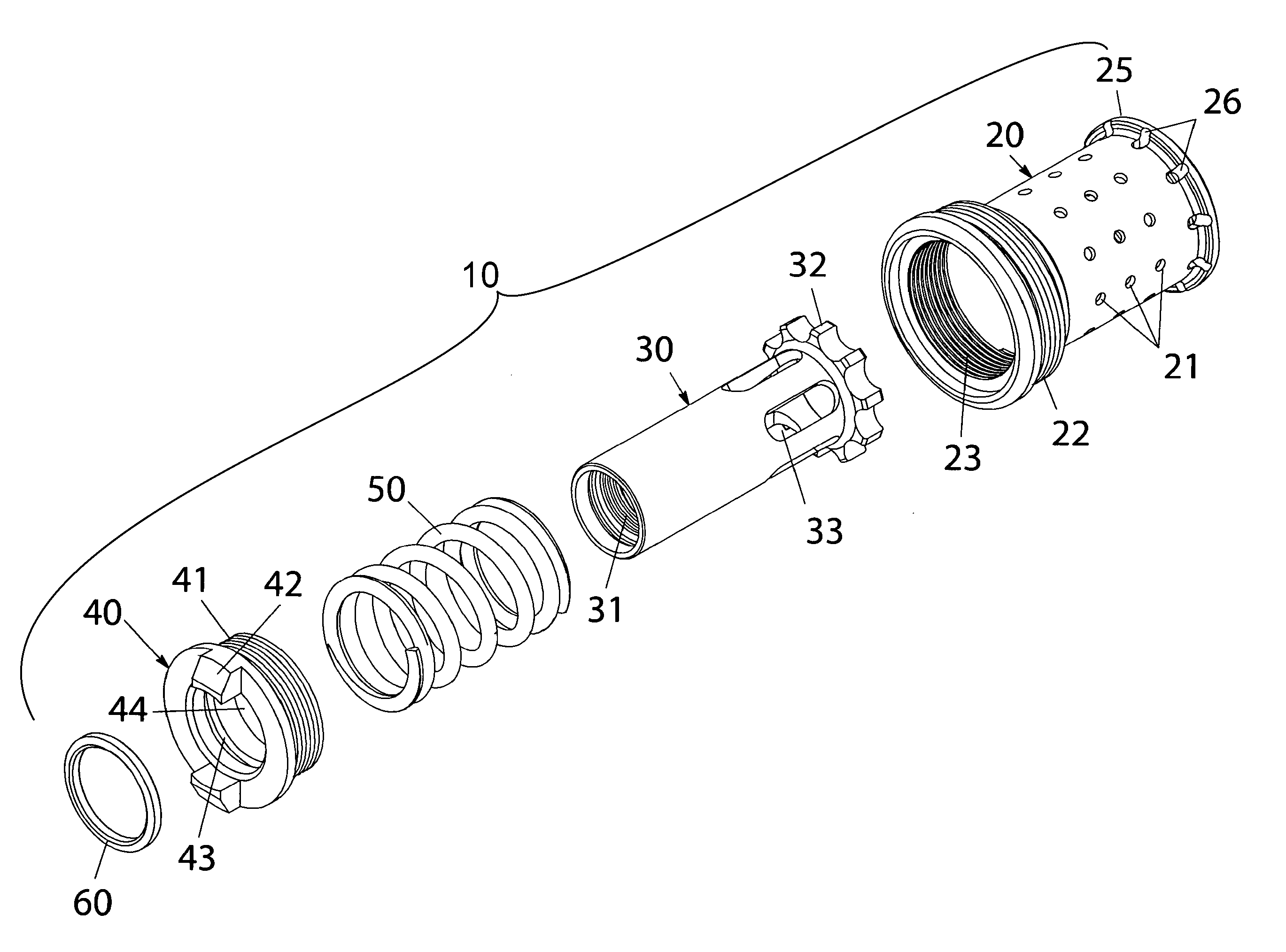
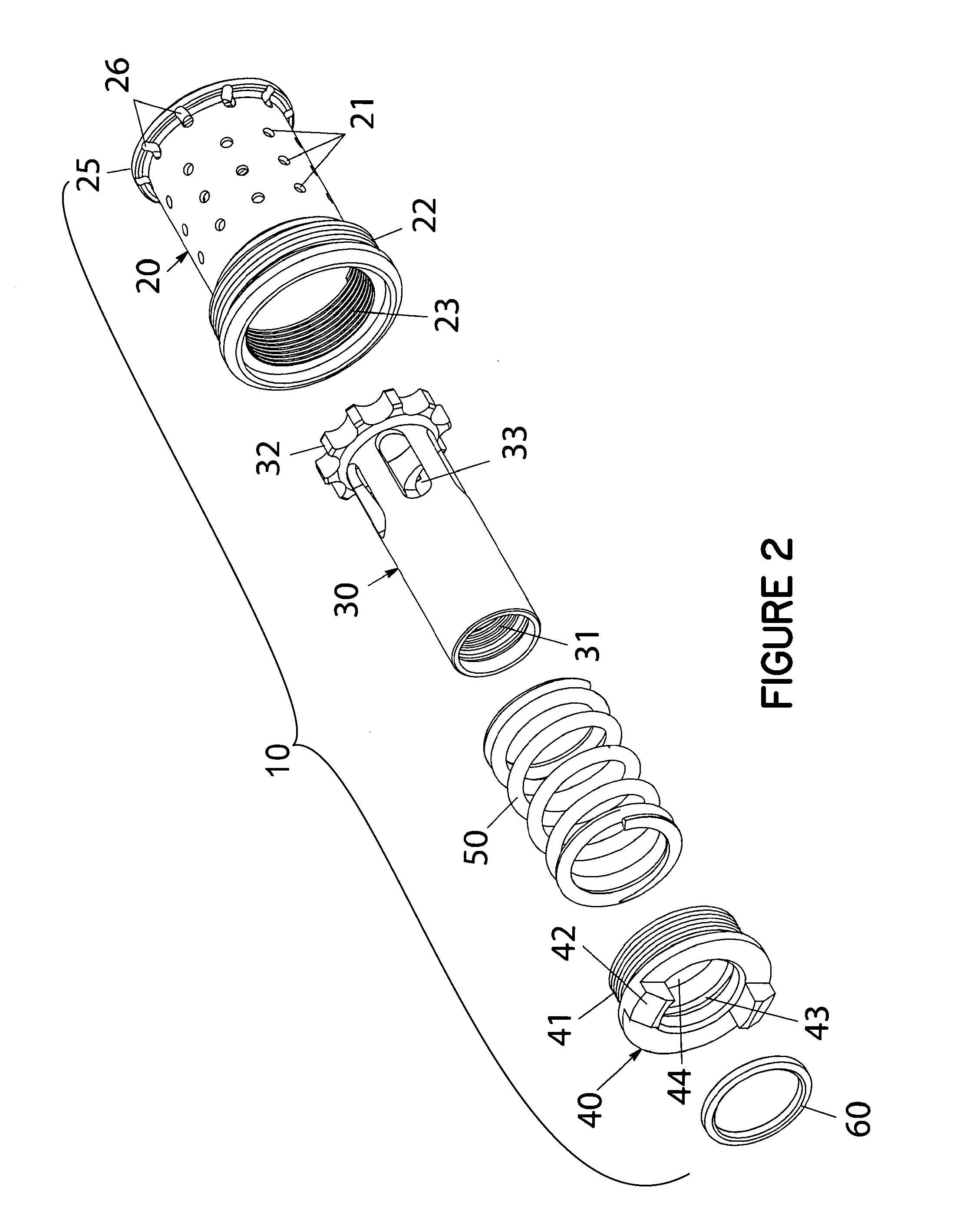
[0025]The herein described invention was designed to improve the functionality of boosters for handgun silencers. The lightweight booster housing, in one embodiment, is threaded into the housing of a silencer. The booster includes a piston, compression spring, housing and rear cap. A piston provides a method for attaching the booster, and thereby the silencer, to a firearm barrel. Textured features have been machined about the exterior of the rear cap to facilitate removably securing the piece onto the booster housing. Also provided are ten indiv

Problems solved by technology

Muzzle flash is harmful to the user's night vision and provides a visual cue as to the location of the person discharging a firearm.
The sound provides a visual cue to the location of a shooter and is harmful to his or her hearing.
As such, the inclusion of a silencer is often problematic.
While there are several designs on the market which function as a reliable booster for Browning inspired designs these designs have other deficiencies.
If improper solvents are used to clean the silencer, the adhesive which holds the screw into the housing can be dissolved allowing the screw to become threadedly unsecured.
The screw is also known to break at times due to manufacturing defects.
Further, the screw utilized only prevents gross rotational movement.
If the silencer is allowed to freely rotate about the piston, the accuracy potential of the hand gun in use is severely diminished.
Another issue is related to the maintenance of the booster assembly.
Further, such tools are generally so specific that there would be no substitute readily available from a source other than the manufacturer.
Still another issue is manufacturing efficiency.
Having to secure a screw into the side of the housing by hand is inefficient and slow.

Method used


Image

  • Adjustable silencer booster with spoked piston engagement shoulder
  • Adjustable silencer booster with spoked piston engagement shoulder
  • Adjustable silencer booster with spoked piston engagement shoulder

Examples


Embodiment Construction

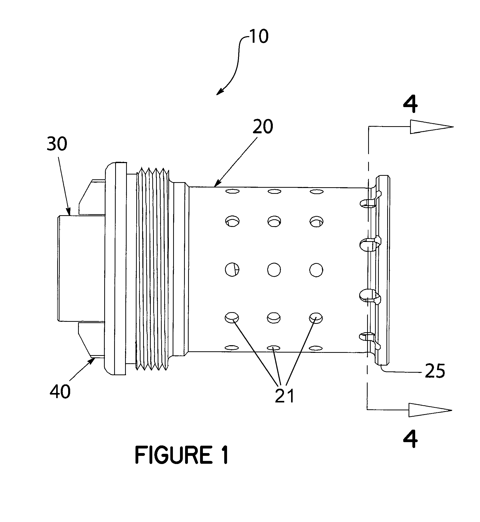
[0033]Turning now to the drawings in which like reference characters indicate corresponding elements throughout the several views, attention is directed to FIG. 1 which illustrates an embodiment of a light weight booster 10 which allows for adjustable orientation of an attached silencer. This embodiment of the herein disclosed invention is comprised of a housing 20, a piston 30, rear cap 40, and compression spring 50 (shown in FIG. 2).

[0034]As used herein, the word “front” or “distal” corresponds to the direction which a discharged projectile would pass through the light weight booster 10 (i.e., to the right as shown in FIGS. 1 thru 3); “rear” or “proximal” or “back” corresponds to the direction opposite the direction of a discharged projectile passing through the light weight booster 10 (i.e., to the left as shown in FIGS. 1 thru 3); “longitudinal” means the direction along or parallel to the longitudinal axis of the light weight booster 10; and “transverse” means a direction perpe...


PUM


Abstract

The herein proposed device relieves an autoloading handguns' barrel from the weight of the silencer allowing it to cycle properly. This improved booster housing for a silencer affords the user ten positions of orientation. A more robust orientation mechanism which minimizes rotational movement of the associated piston when it is fully seated within the booster housing is provided for. Increased accuracy of the host firearm is achieved through the minimization of rotational play. My improved booster housing design is lighter in weight than other similar designs and utilizes a coaxial expansion chamber between the housing and the interior of the silencer tube to increase sound reduction.

Description

BACKGROUND OF THE INVENTION[0001]1. Field of Invention[0002]This invention relates in general to silencers and in particular to devices which are utilized with silencers, to alleviate the weight of a silencer, to allow the proper semi automatic function of a handgun which utilizes a Browning inspired operating system.[0003]2. Prior Art[0004]Silencers for handguns are well known in the prior art and have been used by the US military forces since World War II. Reducing the recoil, muzzle flash, and sound signature of the host firearm through the use of a silencer offers many advantages to the user. Muzzle flash is harmful to the user's night vision and provides a visual cue as to the location of the person discharging a firearm. The sound provides a visual cue to the location of a shooter and is harmful to his or her hearing. Silencers mitigate or eliminate these concerns. The device herein described is a booster which is utilized with a silencer to assist in the proper semi auto func...

Claims


Application Information

Patent Timeline
IPC IPC(8): F41A21/30
CPCF41A21/30
Inventor SMITH, MIKE
Owner JJE BRANDS LLC
Learn More