
Pre-loaded IOL insertion system

a technology of iol and insertion system, which is applied in the field of pre-loaded iol insertion system, can solve the problems of manual iol transfer, less training, and difficulty in maintaining both sterility of iol and correctness, and achieves the effect of less training and less failure ra

Active Publication Date: 2012-09-25
JOHNSON & JOHNSON SURGICAL VISION INC
View PDF99 Cites 62 Cited by
  • Summary
  • Abstract
  • Description
  • Claims
  • Application Information

AI Technical Summary

Benefits of technology

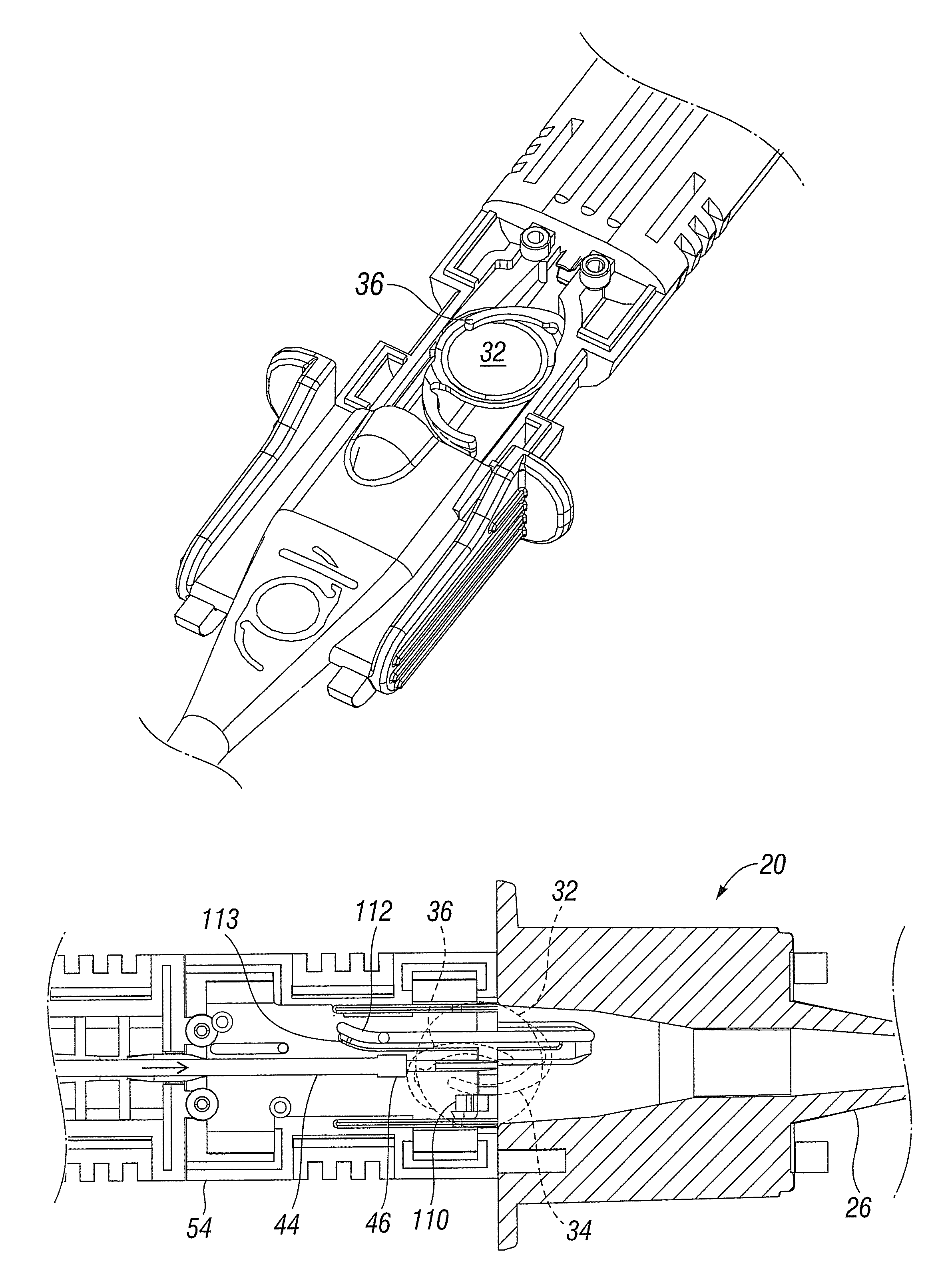
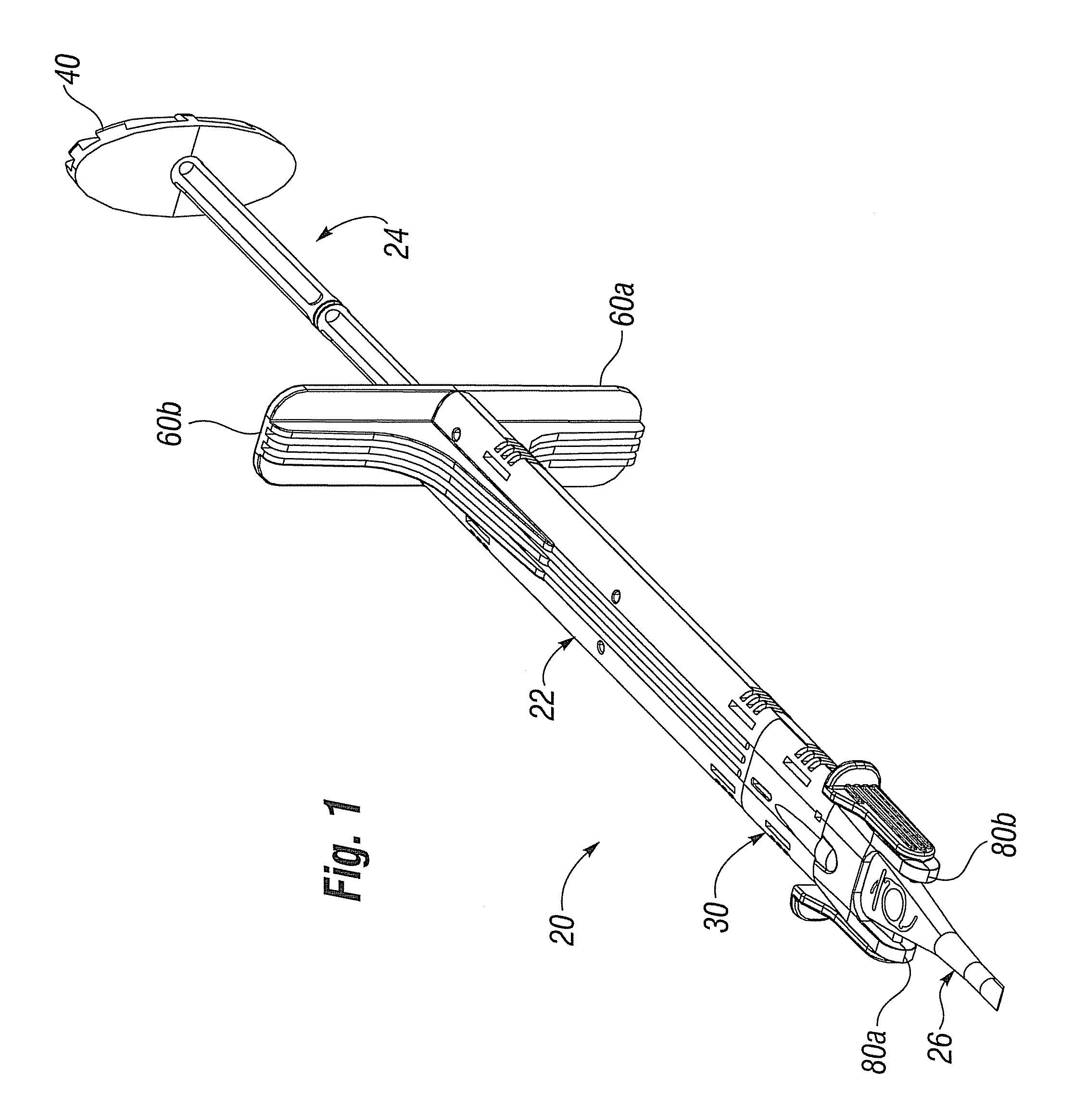
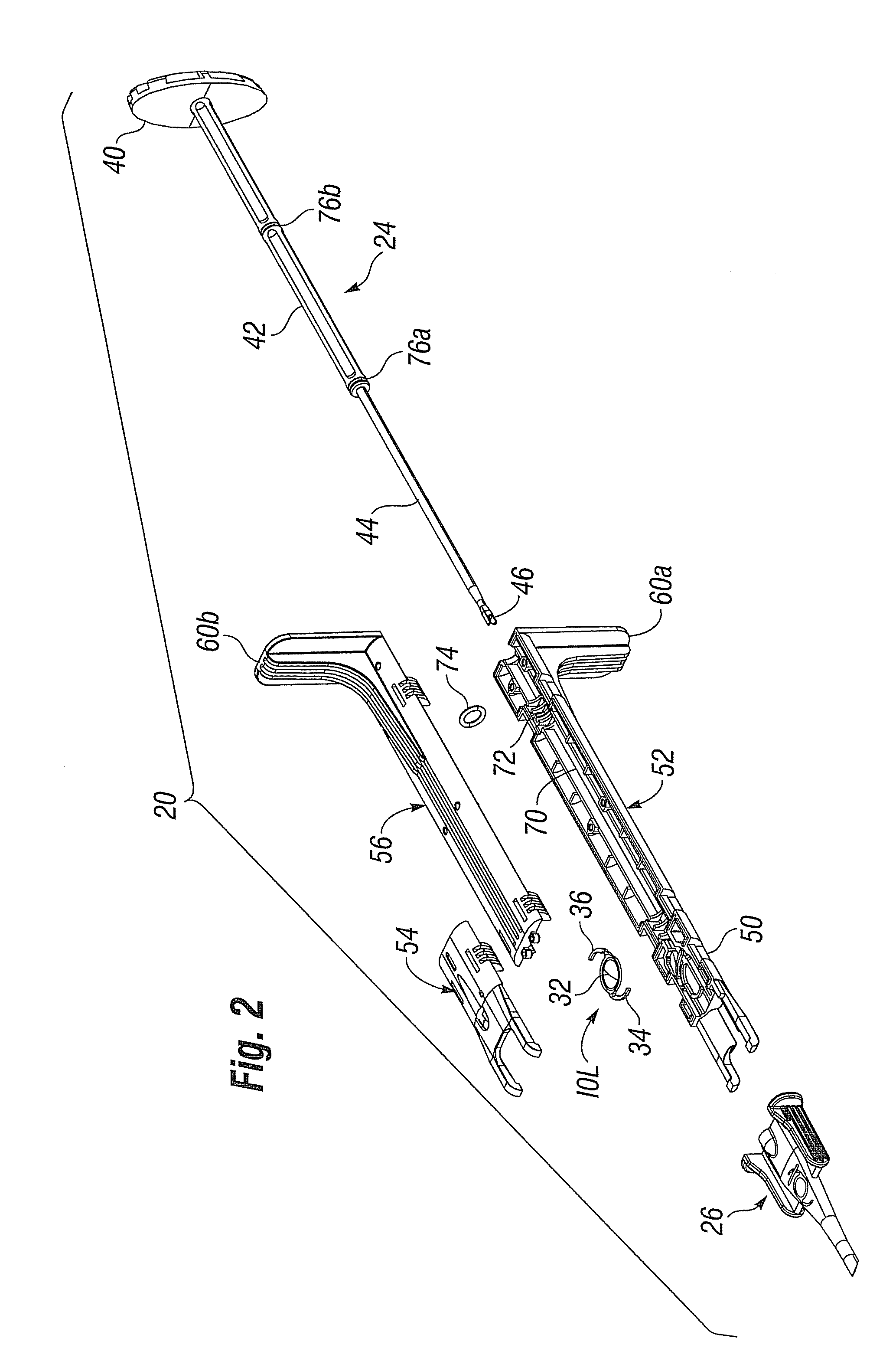
The present invention relates to devices, systems, and methods for delivering an intraocular lens (IOL) into the eye of a patient. The invention addresses issues associated with previous methods, such as difficulty in positioning the IOL and unfolding the haptics, by providing a holding station with internal features that contact the leading and trailing haptics of the IOL as it is displaced in the distal direction. The invention also includes an actuator that displaces the IOL in a distal direction and a delivery tube that has an open proximal end for receiving the IOL. The invention simplifies the assembly process of the IOL insertion system and makes it easier to deliver an IOL into the eye of a patient.

Problems solved by technology

A cataract is a clouding of the eye's lens that impairs a person's vision and, if left untreated, causes blindness.
One problem encountered with existing inserters is difficulty in loading the IOL into the inserter or cartridge.
Manual transfer of the IOL presents difficulties in maintaining both sterility of the IOL and the correct orientation of the IOL, especially the haptics, within the cartridge or inserter.
A wide variety of performance and outcomes results even with highly skilled personnel, and those having less training are more likely to perform poorly.
Improper orientation of the IOL can result in inadequate surgeon control and even damage to the IOL during delivery into the eye.

Method used


Image

  • Pre-loaded IOL insertion system
  • Pre-loaded IOL insertion system
  • Pre-loaded IOL insertion system

Examples


Embodiment Construction

[0026]The present invention facilitates the process of delivering an intraocular lens (IOL) into a patient's eye using an inserter. The IOL is typically implanted using an injector that rolls, folds, or otherwise configures the lens for delivery through a small incision in the eye in a way that reduces trauma and expedites post-surgery healing. The IOL is stored and transferred to a funnel-shaped delivery tube just prior to delivery. The injector or injector / cartridge is generally used in a manner like a hypodermic needle, with the IOL being injected into the eye through a delivery tube. The injector, cartridge and / or delivery tube may be first partially filled with a liquid or gel lubricating agent, for example a viscoelastic material. These are commonly used techniques for delivering an IOL into a patient's eye, and the present invention will be described in the same context. However, it should be understood that certain principles of the present invention can apply to modified sy...


PUM

PropertyMeasurementUnit
diameteraaaaaaaaaa
aspect ratioaaaaaaaaaa

Abstract

A system for easily transferring an intraocular lens (IOL) from an inserter into a patient's eye. The system includes an inserter handpiece with a holding station for receiving or storing an IOL. The IOL may be pre-loaded within the holding station during manufacture, and the inserter handpiece coupled to a delivery tube so that the entire system is ready for use by a surgeon to implant an IOL. The IOL may have an optic and leading and trailing haptics coupled to the optic, and the holding station may be capable of manipulating the haptics as desired to facilitate transfer of the IOL through the delivery tube into the eye. For instance, the holding station may fold one or both of the haptics over the optic. Preferably, the holding station maintains the haptics in their folded positions during transfer of the IOL into the delivery tube. The holding station desirably maintains the IOL in a relaxed configuration during storage. A small opening on one side may be provided to introduce a narrow tool for folding one of the haptics over the optic.

Description

FIELD OF THE INVENTION[0001]The present invention relates to devices, systems, and methods for delivering an intraocular lens into an eye. More particularly, the invention relates to devices, systems, and methods in which the intraocular lens is loaded into the front end of the device.BACKGROUND OF THE INVENTION[0002]It is estimated that 73% of Americans between the ages of 65 to 74 get cataracts. A cataract is a clouding of the eye's lens that impairs a person's vision and, if left untreated, causes blindness. As a result, each year approximately 1.4 million people in the United States alone undergo cataract surgery, whereby the clouded natural crystalline lens is removed and replaced with an intraocular lens (IOL) implant.[0003]Surgeons implant IOLs not only as a replacement for the natural crystalline lens but also to alter the optical properties of (provide vision correction to) an eye in which the natural lens remains. IOLs often include an optically clear disk-like optic of ab...

Claims


Application Information

Patent Timeline
Patent Type & Authority Patents(United States)
IPC IPC(8): A61F2/16
CPCA61F2/1664A61F2/167Y10T29/49826A61F2/1691
Inventor ANDERSON, STEVEN R.
Owner JOHNSON & JOHNSON SURGICAL VISION INC
Learn More