Modulator and modulation method for a wireless data transmission device

a wireless data transmission and modulator technology, applied in wave based measurement systems, instruments, reradiation, etc., can solve the problems of base station not being able to detect the phase modulated signal power reflected by the transponder may decrease, and use to a limited extent for greater distances

Active Publication Date: 2012-09-25
ATMEL CORP
View PDF13 Cites 5 Cited by
  • Summary
  • Abstract
  • Description
  • Claims
  • Application Information

AI Technical Summary

Benefits of technology

[0011]It is therefore an object of the present invention to provide, for wireless data communication, modulation that is efficient and as reliable as possible, wherein modulation of the returned carrier wave is accomplished by means of a rectifier.
[0016]The advantage of the intervention in the AC node and DC node is that discharging of the support capacitor at the output of the rectifier circuit is automatically prevented by the inventive modified modulator in that a following diode is polarized in the reverse direction as soon as the voltage in the rectifier stage acted on by the modulation becomes lower. In addition, investigations by the applicant have shown that the efficiency of intervention by the controllable switching device in an AC node is even higher than when it intervenes in a DC node of the rectifier circuit. The inventive modulation is thus especially advantageous for PSK modulation, in particular when only small amounts of energy are available for the transponder in the far field by means of the rectifier.
[0017]Furthermore, the inventive modulation additionally offers a very reliable modulation that is also very flexible in combination with ASK modulation, since an efficient modulation is provided here for both ASK modulation and PSK modulation.

Problems solved by technology

ASK modulation is thus especially suitable for short distances between the base station and transponder, but is only usable to a limited extent for greater distances.
However, the power reflected by the transponder may decrease when the distance between the transponder and base station is reduced.
At very small distances, the situation can arise that the base station can no longer detect the phase modulated signal reflected by the transponder.
Thus, PSK modulation may not be optimal for very short distances between the base station and the transponder.
This solution places a considerable load on the switching unit of this DC node, and in particular can only be used with passive, especially backscatter-based, transponder systems when high energy absorption by the transponder from the electromagnetic field is possible in the near field, i.e. at very short distances.

Method used


Image

  • Modulator and modulation method for a wireless data transmission device
  • Modulator and modulation method for a wireless data transmission device
  • Modulator and modulation method for a wireless data transmission device

Examples


Embodiment Construction

[0039]In the drawings, like or functionally like elements and signals are identified with the same reference labels, unless otherwise specified.

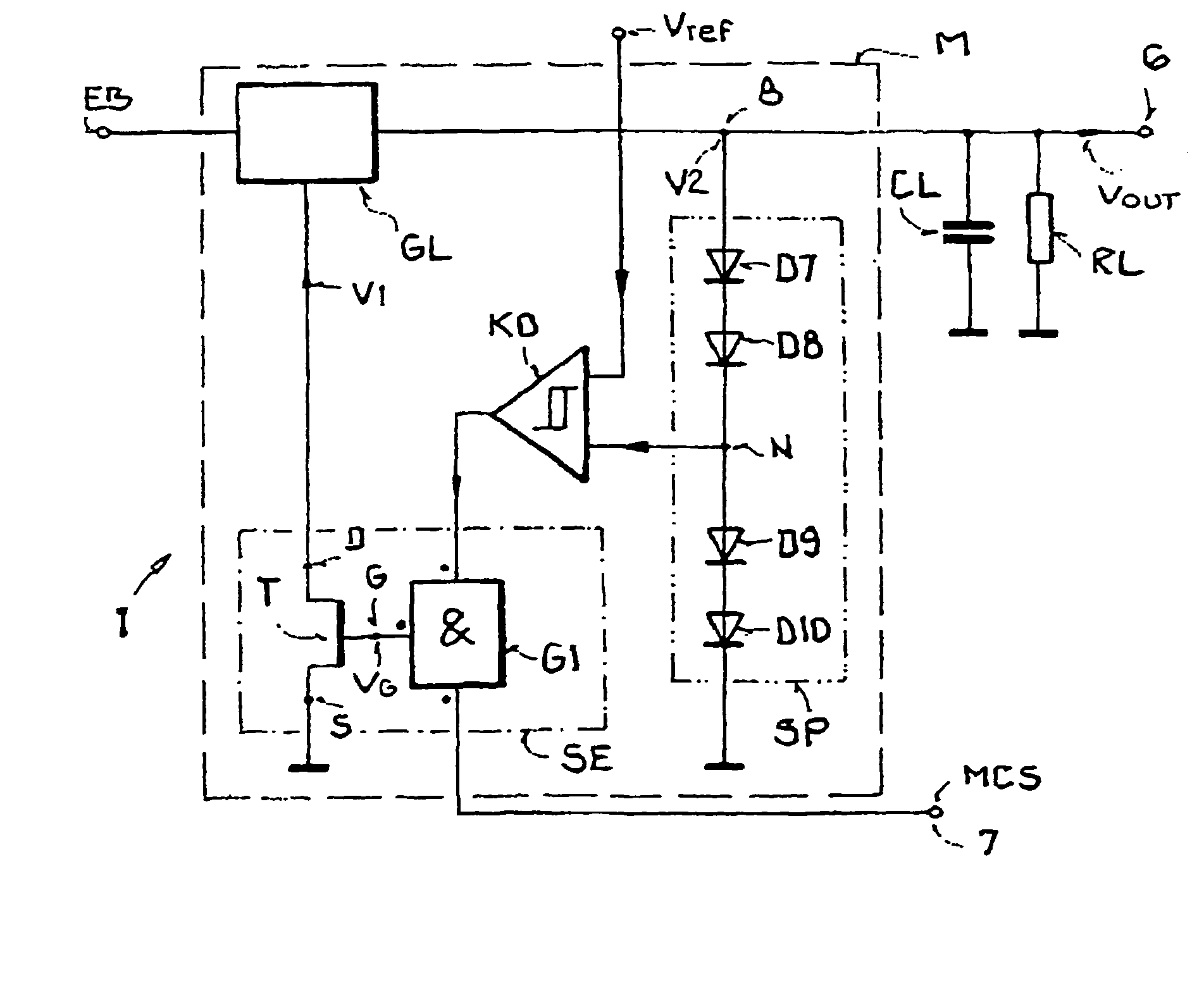
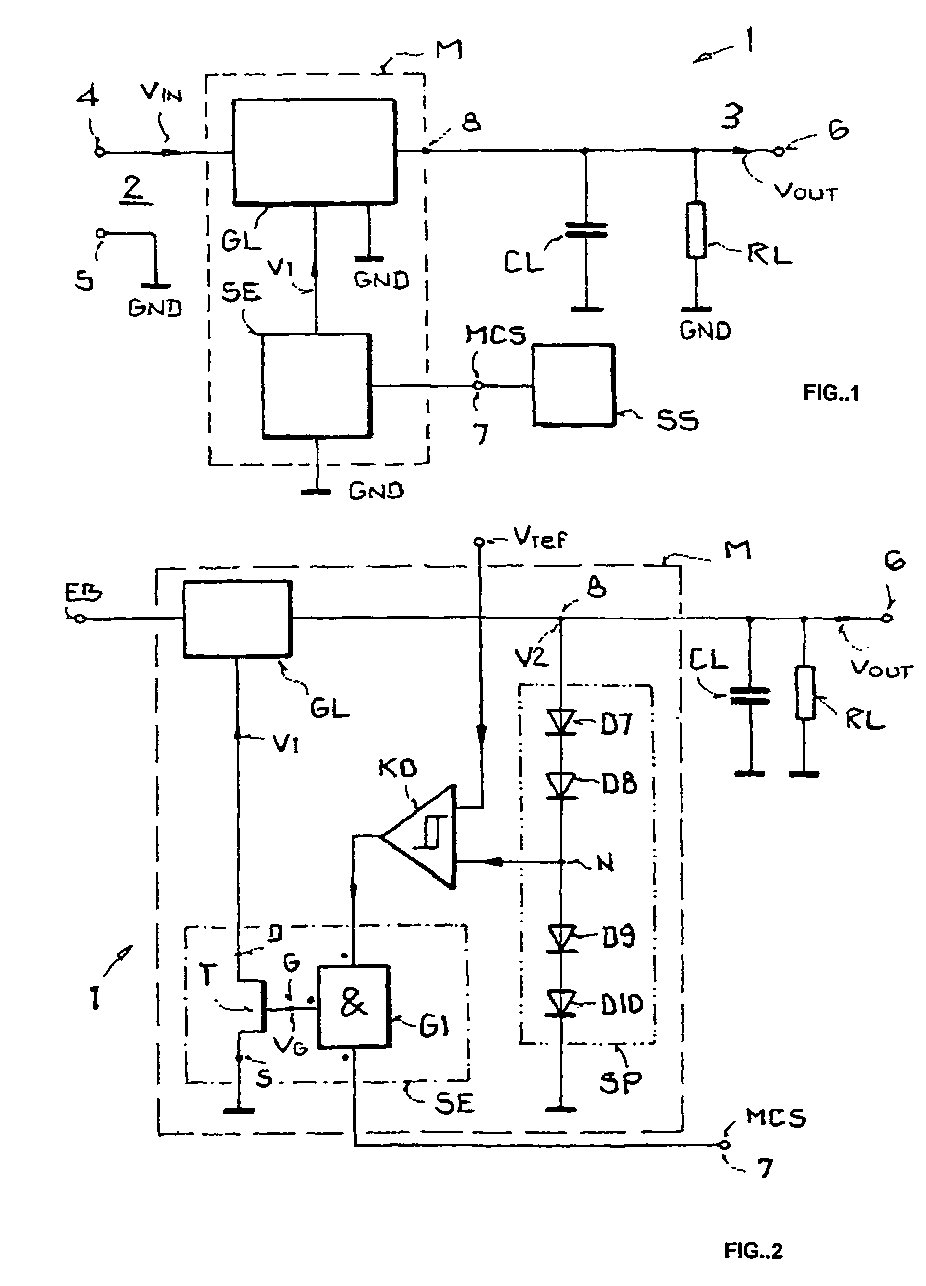
[0040]FIG. 1 uses a block diagram to depict a first, general arrangement with an inventive modulator, showing a transmitting and receiving device, labeled with reference symbol 1, for a passive or semi-passive transponder whose purpose is bidirectional communication with a base station which is not shown in FIG. 1.

[0041]The transmitting and receiving device 1 has an input 2 and an output 3. The input 2 has a first and a second input connection 4, 5, wherein an input voltage VIN is applied to the first input connection 4 and a reference voltage, for example the reference ground potential GND, is applied to the second input connection 5. The input voltage VIN is, for example, the electromagnetic carrier signal transmitted by a base station and received by the transponder or a signal derived therefrom. At the output 3, an output connection 6 is...


PUM


Abstract

In certain embodiments, an apparatus includes a rectifier and a switch. The rectifier is configured to modulate a received carrier signal. The switch is coupled to at least one node of the rectifier. The switch is configured to modify an impedance of the rectifier to modulate the received carrier signal by providing a potential to the at least one node of the rectifier based on a field strength of the received carrier signal and a modulation-control signal.

Description

[0001]This nonprovisional application is a continuation of International Application PCT / EP2005 / 007496, which was filed on Jul. 11, 2005, and which claims priority to German Patent Application No. DE 102004033782, which was filed on Jul. 12, 2004, and which are all herein incorporated by reference.BACKGROUND OF THE INVENTION[0002]1. Field of the Invention[0003]The present invention relates to a modulator for data transmission between a transponder and a base station, which amplitude modulates and / or phase modulates a received electromagnetic carrier signal as a function of data to be transmitted. The invention further relates to a transponder having such a modulator, and a modulation method for operating such a modulator.[0004]2. Description of the Background Art[0005]The invention resides in the field of transponder technology and more particularly in the field of contactless communication for the purposes of identification. Although applicable in principle to any desired communica...

Claims


Application Information

Patent Timeline
Patent Type & Authority Patents(United States)
IPC IPC(8): H04Q5/22
CPCG06K7/0008G06K19/0723
Inventor FRIEDRICH, ULRICHFISCHER, MARTINPANGELS, MICHAEL
Owner ATMEL CORP
Why Eureka
Try Eureka