
Apparatus and a method for decoding an encoded audio signal

a technology of encoded audio and apparatus, applied in the field of apparatus for encoding, encoding and audio signal, can solve the problems of limiting the amr-wb+ audio quality factor, the frequency domain audio coder fails to deliver decent quality for some general audio signals, and the quality of music signals at low bit rate is not good, so as to achieve the effect of higher perceptual quality

Active Publication Date: 2012-09-25
FRAUNHOFER GESELLSCHAFT ZUR FOERDERUNG DER ANGEWANDTEN FORSCHUNG EV
View PDF36 Cites 33 Cited by
  • Summary
  • Abstract
  • Description
  • Claims
  • Application Information

AI Technical Summary

Benefits of technology

The patent describes an apparatus and method for decoding and encoding audio signals using different encoding algorithms and bandwidth extension parameters. The apparatus includes a decoder and a BWE module with a controllable crossover frequency for performing bandwidth extension. The method involves decoding the audio signal using the appropriate encoding algorithm and BWE parameters for each portion of the signal. The technical effect of this invention is improved audio quality and flexibility in decoding and encoding options.

Problems solved by technology

A limiting factor to AMR-WB+ audio quality is the audio bandwidth common to both core codecs and BWE start frequency that is one quarter of the system's internal sampling frequency.
While the ACELP speech model is capable to model speech signals quite well over the full bandwidth, the frequency domain audio coder fails to deliver decent quality for some general audio signals.
Thus, speech coding schemes show a high quality for speech signals even at low bit rates, but show a poor quality for music signals at low bit rates.
Problematic, however, is the quality of speech signals at low bit rates.
A straightforward way would be to find the lowest of all core coder bandwidths and use this as BWE start frequency, but this would deteriorate the perceived audio quality.

Method used


Image

  • Apparatus and a method for decoding an encoded audio signal
  • Apparatus and a method for decoding an encoded audio signal
  • Apparatus and a method for decoding an encoded audio signal

Examples


Embodiment Construction

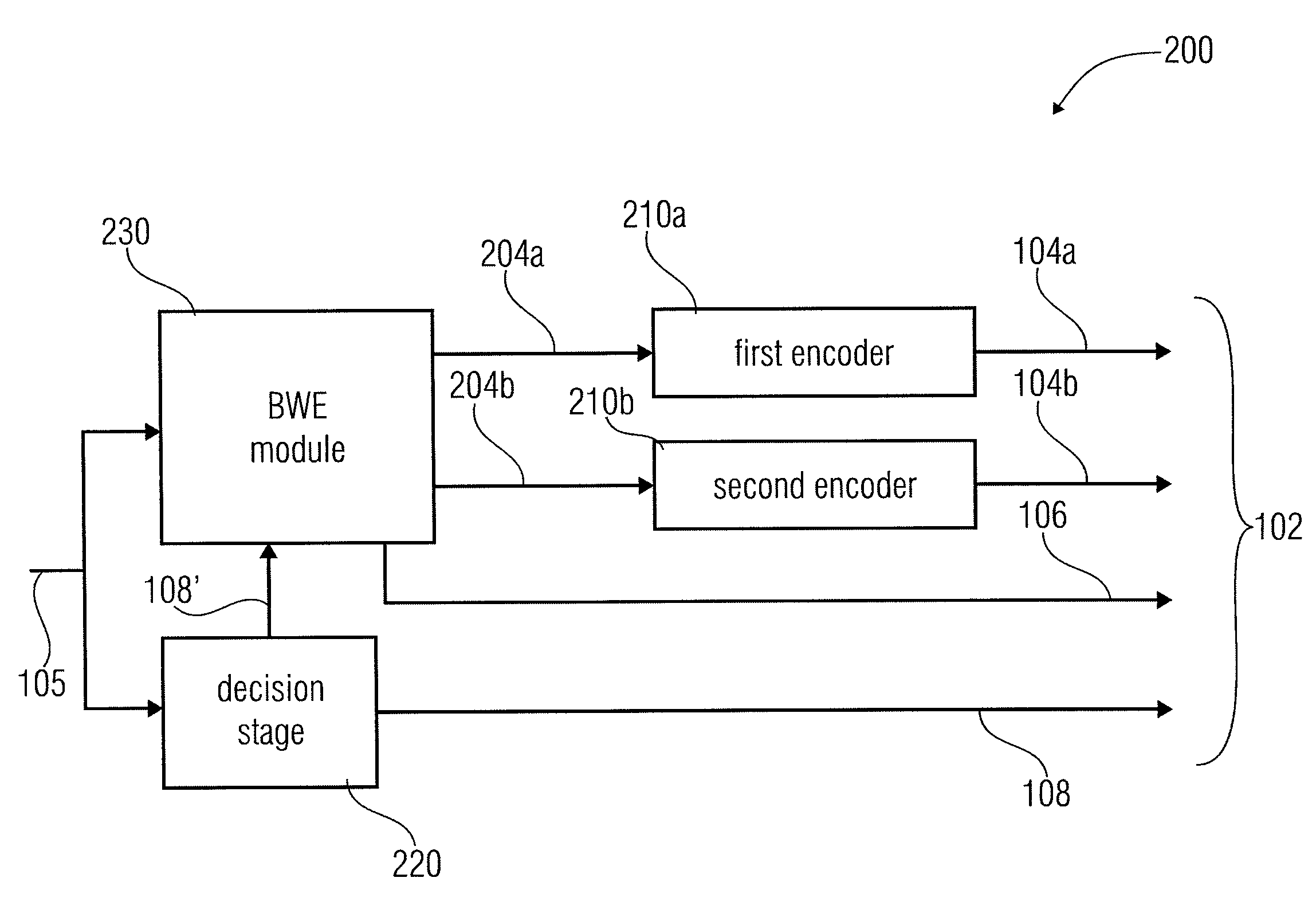
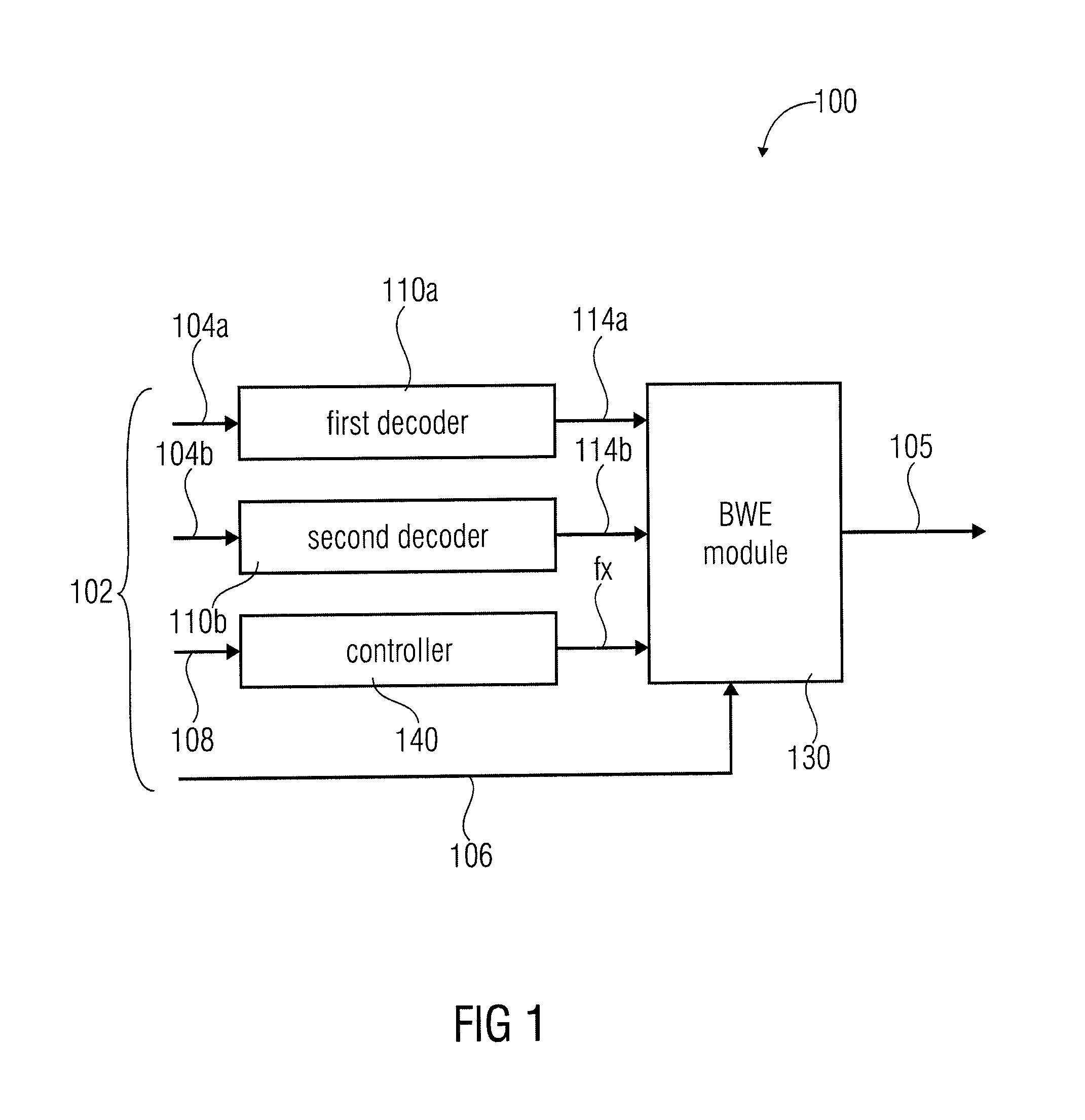
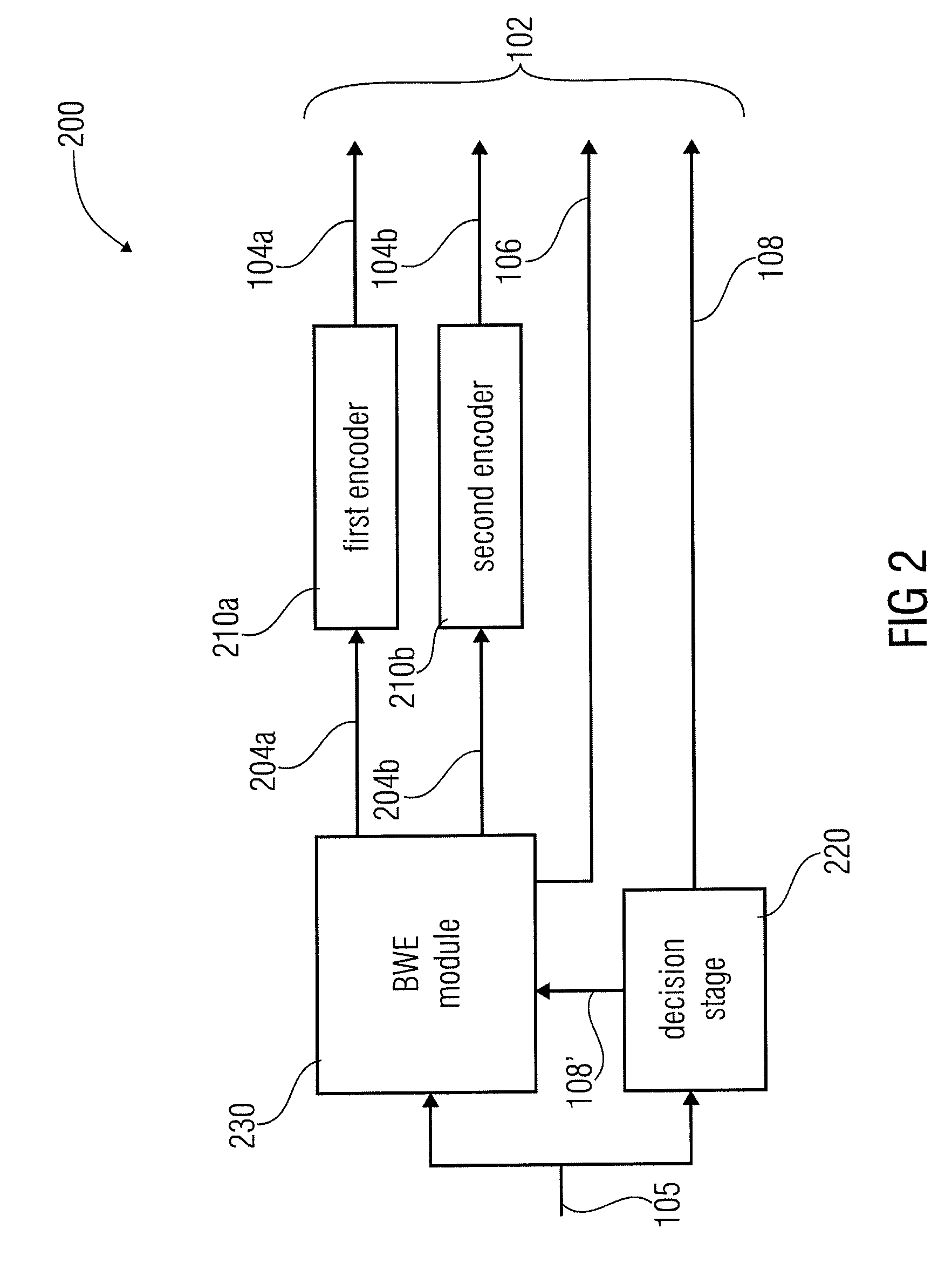
[0033]FIG. 1 shows a decoder apparatus 100 for decoding an encoded audio signal 102. The encoded audio signal 102 comprising a first portion 104a encoded in accordance with the first encoding algorithm, a second portion 104b encoded in accordance with a second encoding algorithm, BWE parameter 106 for the first time portion 104a and the second time portion 104b and a coding mode information 108 indicating a first decoding algorithm or a second decoding algorithm for the respective time portions. The apparatus for decoding 100 comprises a first decoder 110a, a second decoder 110b, a BWE module 130 and a controller 140. The first decoder 110a is adapted to decode the first portion 104a in accordance with the first decoding algorithm for a first time portion of the encoded signal 102 to obtain a first decoded signal 114a. The second decoder 110b is configured to decode the second portion 104b in accordance with the second decoding algorithm for a second time portion of the encoded sign...


PUM


Abstract

An apparatus for decoding an encoded audio signal having first and second portions encoded in accordance with first and second encoding algorithms, respectively, BWE parameters for the first and second portions and a coding mode information indicating a first or a second decoding algorithm, includes first and second decoders, a BWE module and a controller. The decoders decode portions in accordance with decoding algorithms for time portions of the encoded signal to obtain decoded signals. The BWE module has a controllable crossover frequency and is configured for performing a bandwidth extension algorithm using the first decoded signal and the BWE parameters for the first portion, and for performing a bandwidth extension algorithm using the second decoded signal and the bandwidth extension parameter for the second portion. The controller controls the crossover frequency for the BWE module in accordance with the coding mode information.

Description

CROSS-REFERENCE TO RELATED APPLICATIONS[0001]This application is a continuation of copending International Patent Application No. PCT / EP2009 / 004522 filed Jun. 23, 2009, and claims priority to U.S. Application No. 61 / 079,841, filed Jul. 11, 2008, and additionally claims priority from U.S. Application 61 / 103,820, filed Aug. 10, 2008, all of which are incorporated herein by reference in their entirety.BACKGROUND OF THE INVENTION[0002]The present invention relates to an apparatus and a method for decoding an encoded audio signal, an apparatus for encoding, a method for encoding and an audio signal.[0003]In the art, frequency domain coding schemes such as MP3 or AAC are known. These frequency-domain encoders are based on a time-domain / frequency-domain conversion, a subsequent quantization stage, in which the quantization error is controlled using information from a psychoacoustic module, and an encoding stage, in which the quantized spectral coefficients and corresponding side informatio...

Claims


Application Information

Patent Timeline
Patent Type & Authority Patents(United States)
IPC IPC(8): G10L19/00
CPCG10L19/20G10L21/04G10L21/038G10L19/008G10L19/022G10L19/0212G10L19/18G10L19/02G10L19/04H03M7/30
Inventor NEUENDORF, MAXGRILL, BERNHARDKRAEMER, ULRICHMULTRUS, MARKUSPOPP, HARALDRETTELBACH, NIKOLAUSNAGEL, FREDERIKLOHWASSER, MARKUSGAYER, MARCJANDER, MANUELBACIGALUPO, VIRGILIO
Owner FRAUNHOFER GESELLSCHAFT ZUR FOERDERUNG DER ANGEWANDTEN FORSCHUNG EV
Learn More