
Telescopic mast system

a telescopic mast and telescopic technology, applied in the field of masts, can solve the problems of low capacity load, air leakage between the mast sections, and the inability to quickly bring down the telescopic mast, so as to reduce the load of the telescopic mast, pull the mast sections, and push the mast sections up relatively quickly

Active Publication Date: 2012-10-02
SERAPID
View PDF12 Cites 16 Cited by
  • Summary
  • Abstract
  • Description
  • Claims
  • Application Information

AI Technical Summary

Benefits of technology

The system allows for rapid and smooth movement of mast sections, supporting high loads while maintaining position without air pressure reliance and resisting foreign object interference, ensuring efficient operation in hostile environments.

Problems solved by technology

One disadvantage of the air powered telescopic mast is that if wind bends the mast such that there is lateral deflection, air will leak out between the mast sections.
Another disadvantage is that the telescopic mast cannot be brought down quickly.
Additionally, speed in lowering the mast is an important factor because these telescopic masts typically have expensive equipment such as a communication device mounted on top of the mast and, in a hostile environment, need to be lowered quickly.
Another disadvantage of the air powered telescopic mast is that it can only support a low capacity load due to the small piston of the pneumatic cylinder.
One disadvantage of the cable powered telescopic mast is that it can only support a low capacity load because of the multiple mast sections, otherwise the cable becomes thick.
Another disadvantage of the cable powered telescopic mast is that there is no control of speed in lowering the mast because the mast relies on gravity to be lowered.
In addition, foreign objects such as ice or sand causes interference with the mast sections and the mast will not lower itself due to gravity.

Method used


Image

  • Telescopic mast system
  • Telescopic mast system
  • Telescopic mast system

Examples


Embodiment Construction

)

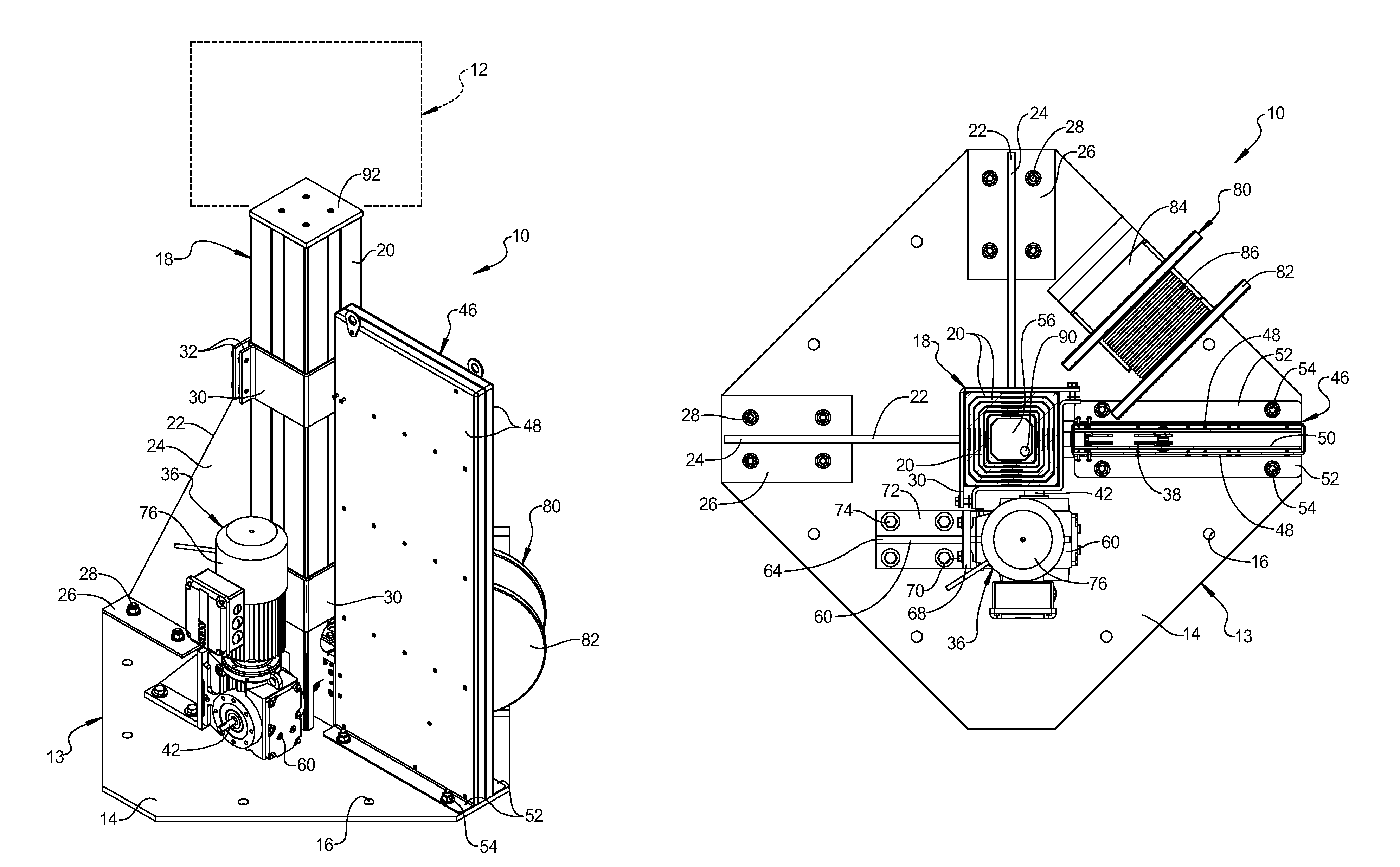
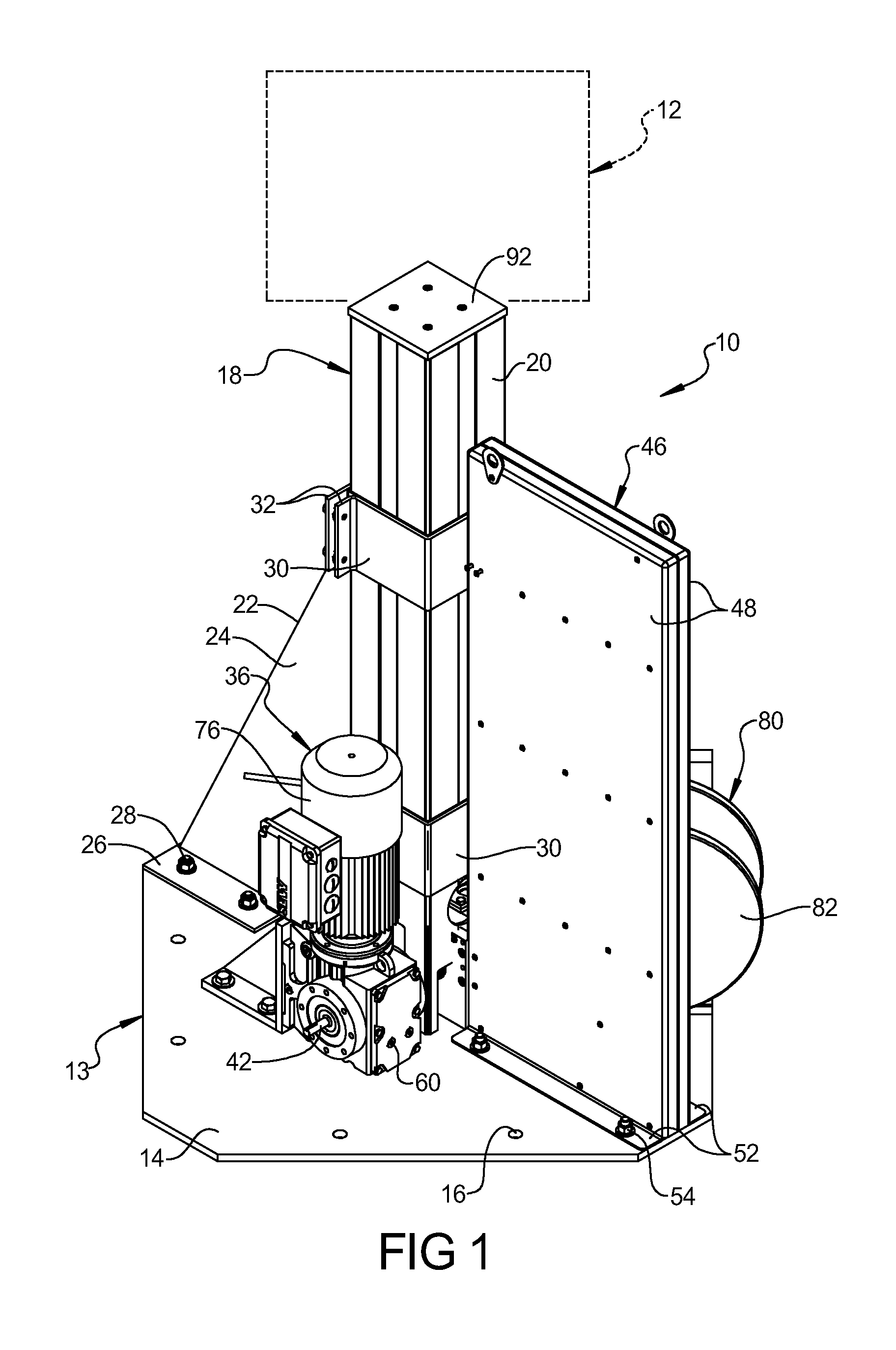
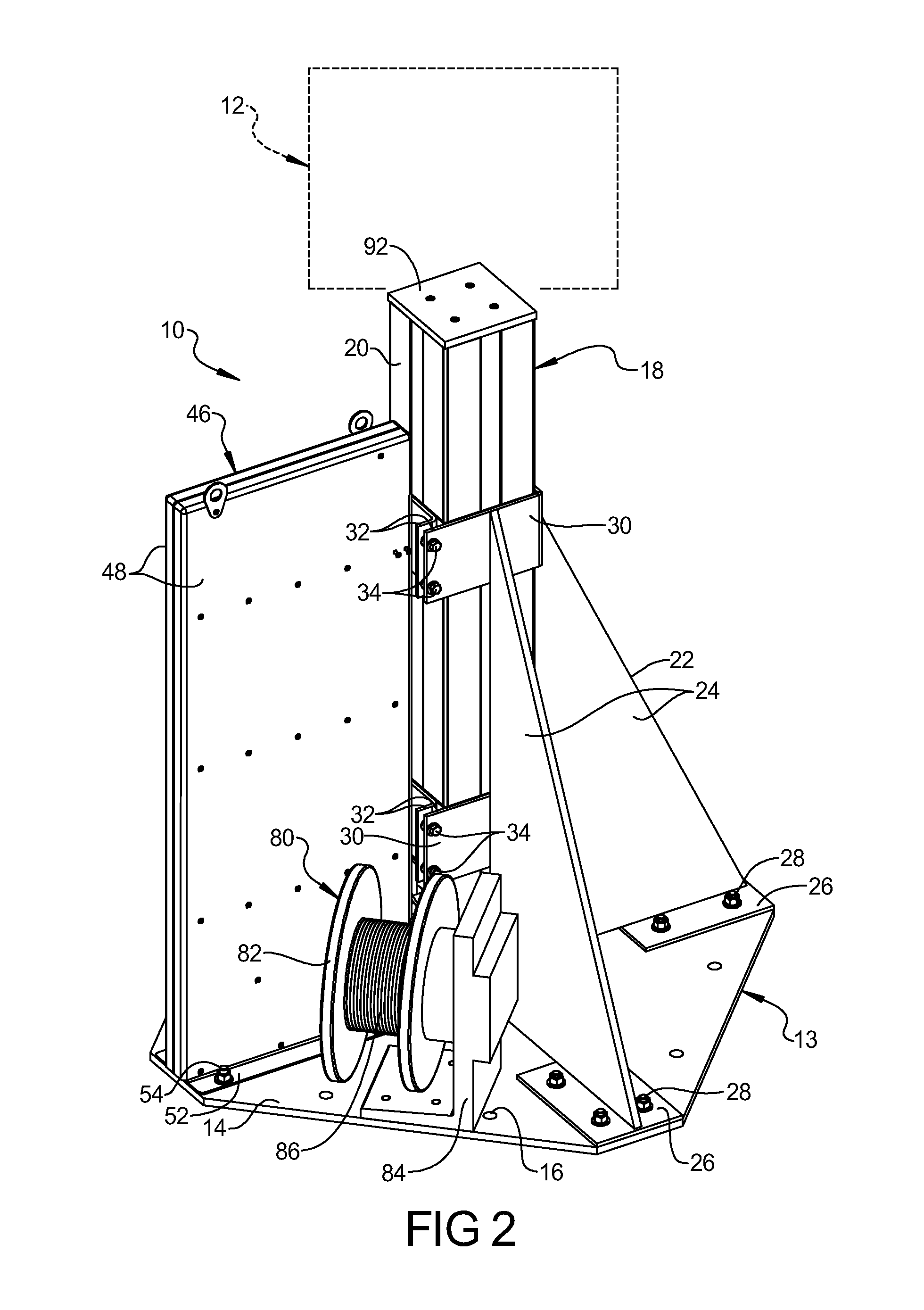
[0022]Referring now to the drawings, and in particular FIGS. 1 through 5, one embodiment of a telescopic mast system 10, according to the present invention, is shown for raising and lowering an object, generally indicated at 12, such as a communications device. The telescopic mast system 10 is supported by a support surface such as ground or in a vehicle (not shown) such as a military vehicle. It should be appreciated that the telescopic mast system 10 is used to quickly raise and lower the object 12. It should also be appreciated that the object 12 may be camera equipment, signage, material handling / manufacturing workstation, surveillance equipment, maintenance platform, personnel platform, etc.

[0023]Referring to FIGS. 1 through 5, the telescopic mast system 10 includes a mounting mechanism, generally indicated at 13, for rigidly mounting the system 10 to the support surface. In one embodiment, the mounting mechanism 13 may include a base 14 such as a plate. The base 14 is general...


PUM


Abstract

A telescopic mast system includes a telescopic mast comprising a plurality of telescopic mast sections and a drive mechanism for extending and retracting the telescopic mast sections. The drive mechanism includes a rigid chain having one end connected to a last one of the telescopic mast sections to move the telescopic mast sections and a plurality of guide plates cooperating with the telescopic mast sections to prevent buckling of the rigid chain.

Description

BACKGROUND OF THE INVENTION[0001]1. Field of the Invention[0002]The present invention relates generally to masts and, more specifically, to a telescopic mast system.[0003]2. Description of the Related Art[0004]It is known to provide a telescopic mast to raise or lower an object such as a communication device, e.g., a surveillance camera. Typically, the telescopic mast includes a plurality of tubular mast sections that may be raised by air or cable power. In the air powered telescopic mast, air is supplied from a source to a pneumatic cylinder that raises the mast sections and when the air is discontinued to the pneumatic cylinder, gravity allows the mast sections to be lowered. In the cable powered telescopic mast, a winch and pulley is used with a cable to raise the mast sections and gravity is allows the mast sections to be lowered.[0005]One disadvantage of the air powered telescopic mast is that if wind bends the mast such that there is lateral deflection, air will leak out betwe...

Claims


Application Information

Patent Timeline
Patent Type & Authority Patents(United States)
IPC IPC(8): B66C23/04E04G1/18E04G1/22B66C23/34
CPCB66F11/00F16M11/18F16M11/26F16M11/28
Inventor LOUNIS, SAIDDOMBROWSKI, KEVIN
Owner SERAPID
Learn More