Radial compressor rotor

a rotor and radial compressor technology, applied in the direction of forging/pressing/hammering equipment, marine propulsion, vessel construction, etc., can solve the problems of limiting the operation range of a radial compressor, unable to ensure stable operation, and unable to use a radial compressor on the other side, so as to improve the flow behavior, stabilize the characteristic of the compressor, and improve the effect of flow behavior

Active Publication Date: 2012-10-02
SIEMENS ENERGY GLOBAL GMBH & CO KG
View PDF6 Cites 6 Cited by
  • Summary
  • Abstract
  • Description
  • Claims
  • Application Information

AI Technical Summary

Benefits of technology

[0013]The advantage of the invention can be seen in particular in the fact that a double-curved surface is better adapted to the three-dimensional development of the flow and therefore an improved flow behavior results. The stable flow behavior leads firstly to the stabilizing of the compressor characteristic and to the increase in the efficiency of the radial compressor.
[0014]In contrast, modern blade surfaces of radial compressor rotors are often defined by means of rectilinear generatrices. The expression “ruled surfaces” or “ruled-surface straight lines” is used in this connection. To produce these surfaces, recourse is normally had to a machining operation by flank milling by means of cylindrical or tapered plain milling cutters. In this case, the milling cutter is brought into engagement in such a way that its ideal generating line in the cutting region is oriented parallel to the respective ruled-surface straight line of the blade surface.
[0015]In a preferred configuration, a further section of the surface of the blades is designed as a ruled-surface section, the generatix of which is designed as a straight line. This section therefore forms a ruled surface, such that at least one straight line runs through each point of this section.
[0016]It is also preferable that the transition from the double-curved section to the ruled-surface section is continuous. There are thus no kinks or edges between these two sections. The transition between these two sections is rounded. This ensures that no turbulence is produced by separation of the flow on account of unevenness on the surface.
[0017]The blades preferably have a hub edge and an approximately opposite outer edge, the double-curved section adjoining the outer edge and the ruled-surface section adjoining the hub edge. The hub edge is an edge adjoining a hub of the wheel disk; it is thus located in the bottom region of the blade. The outer edge lies approximately opposite the hub edge. In half-open rotors, it is designed as a free edge. In closed rotors, it adjoins the cover disk. The outer edge, hub edge, leading edge and trailing edge define the blade, the outer edge and the hub edge each connecting the leading edge to the trailing edge.
[0018]The double-curved section and / or the ruled-surface section expediently extends from the leading edge up to the trailing edge.

Problems solved by technology

However, the operating range of a radial compressor is restricted by the “surge limit”.
The radial compressor can no longer be used on the other side of the surge limit, for the flow separates from the blades and stable operation can no longer be ensured.
In these embodiments, the entire surface is designed as a sculptured surface, a factor which firstly is complicated with regard to the description of the geometry and secondly involves a high production cost.
A blade produced in such a way cannot take into account the complexity of a three-dimensional flow.

Method used


Image

  • Radial compressor rotor
  • Radial compressor rotor
  • Radial compressor rotor

Examples


Embodiment Construction

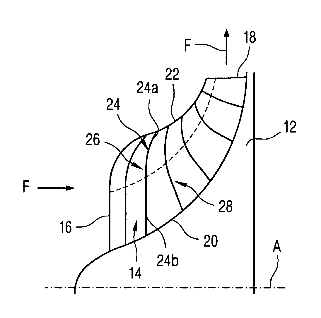
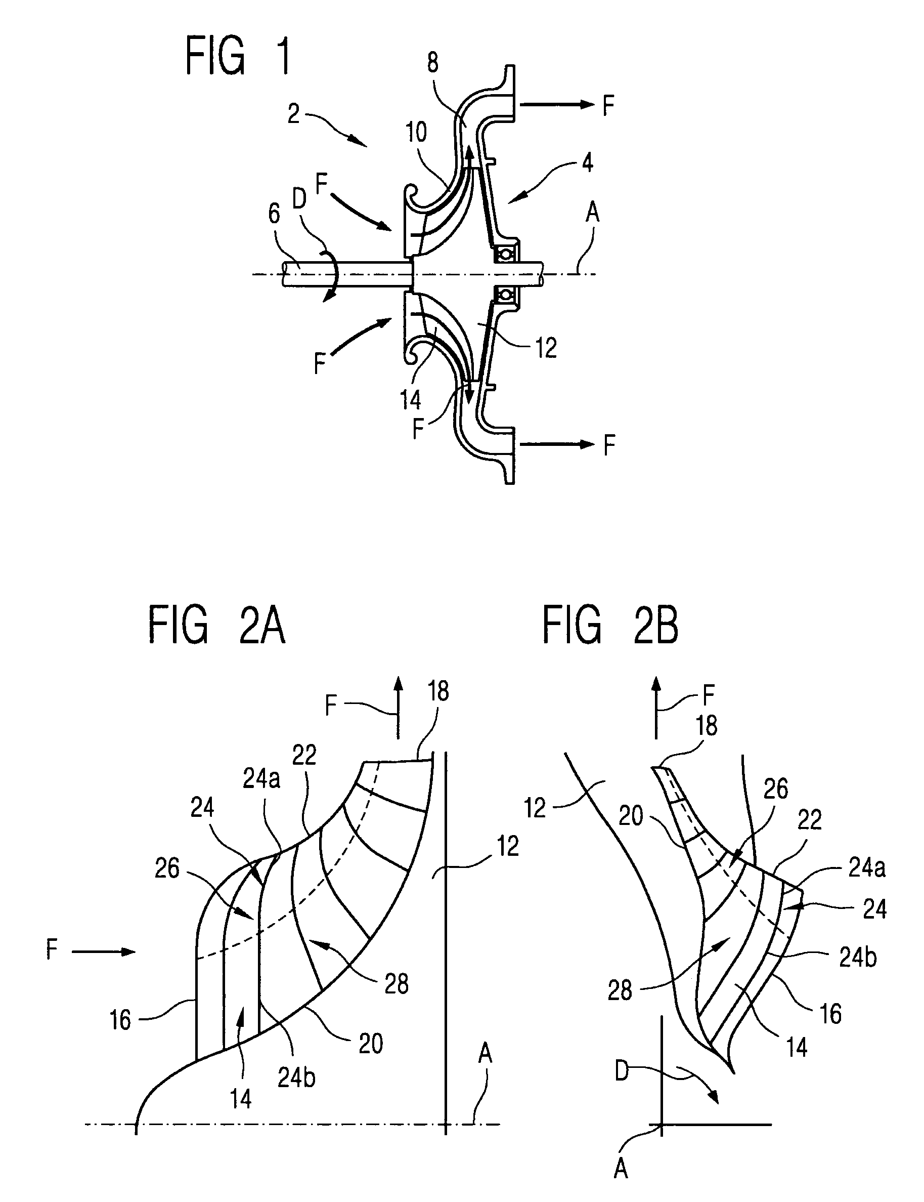
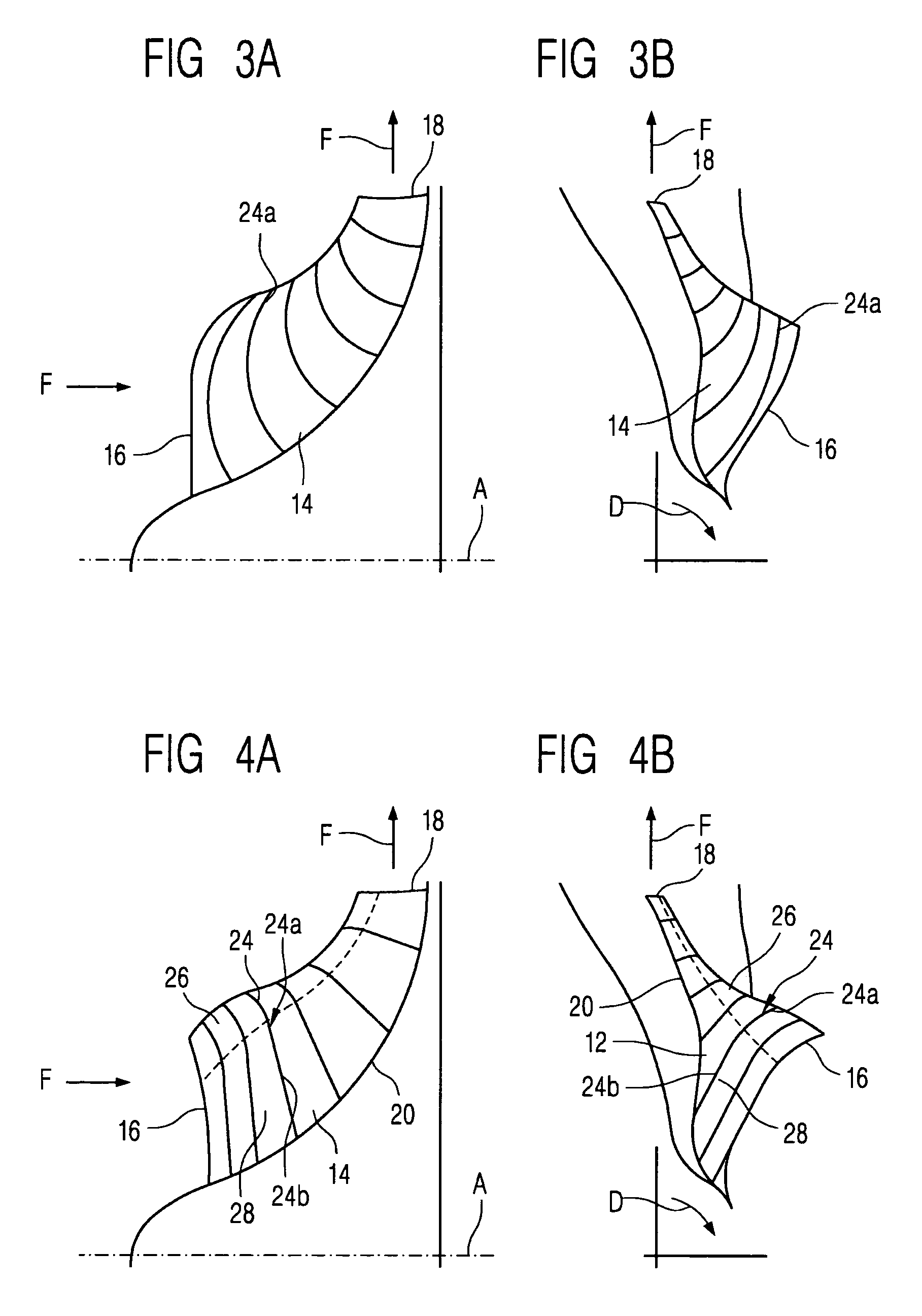
[0041]A radial compressor 2 working in a single-flow manner (delivery gas feed only from one side) and in a single-stage manner is shown in FIG. 1. The radial compressor 2 comprises a rotor 4, a shaft 6, which rotates in rotation direction D and on which the rotor 4 is attached and which defines an axial direction A, and a diffuser 8 and a cover disk 10. The rotor 4 consists of a wheel disk 12 and a plurality of blades 14 arranged over the circumference.

[0042]The delivery gas is drawn in axially in the region of the shaft 6 and is accelerated radially outward by the centrifugal force through the passages produced between the blades. This is indicated by the arrows F, which specify the flow direction of the delivery gas. In the process, both the velocity and the pressure of the delivery gas increase. The flow is decelerated in the diffuser 8, which leads to a further increase in the pressure of the delivery gas. After the compression, the delivery gas leaves the radial compressor aga...


PUM

PropertyMeasurementUnit
sizeaaaaaaaaaa
mechanical energyaaaaaaaaaa
pressure energyaaaaaaaaaa

Abstract

A radial compressor rotor is provided for stabilizing the flow behavior of a delivery gas, consisting of a wheel disc and blades arranged uniformly in the circumferential direction, wherein the generatrix of the surface of the blades is designed as a curved line at least in a curved section, such that the surface is curved in two directions in this section.

Description

CROSS REFERENCE TO RELATED APPLICATIONS[0001]This application is the US National Stage of International Application No. PCT / EP2006 / 067919, filed Oct. 30, 2006 and claims the benefit thereof. The International Application claims the benefits of European application No. 05025048.9 filed Nov. 16, 2005, both of the applications are incorporated by reference herein in their entirety.FIELD OF INVENTION[0002]The invention relates to a radial compressor rotor, consisting of a wheel disk and blades which are arranged uniformly in the circumferential direction and have a leading edge and a trailing edge, at least one section of the surface of the blades being a double-curved section, the generatix of which is designed as a curved line, and the curved section likewise being curved perpendicularly to the generatix. The invention also relates to a method of producing a radial compressor rotor of this type.BACKGROUND OF THE INVENTION[0003]Radial compressors convert mechanical energy into pressure...

Claims


Application Information

Patent Timeline
Patent Type & Authority Patents(United States)
IPC IPC(8): B63H1/16F03D11/00F01D5/22B64C11/00B64C27/20
CPCF04D29/284F04D29/30Y10T29/49321
Inventor SCHLUTER, LARSWALLMANN, THEODOR
Owner SIEMENS ENERGY GLOBAL GMBH & CO KG
Why Eureka
Try Eureka