
Electric motor drive device, control method of electric motor drive device, and electrically driven device

a technology of electric motor and control method, which is applied in the direction of motor/generator/converter stopper, dynamo-electric converter control, instruments, etc., can solve the problems of energy conversion efficiency failure and other problems, and achieve the effect of accurate estimation of induced voltage, improving energy conversion efficiency, and reducing the number of parts

Active Publication Date: 2012-10-02
DENSO CORP
View PDF13 Cites 7 Cited by
  • Summary
  • Abstract
  • Description
  • Claims
  • Application Information

AI Technical Summary

Benefits of technology

This configuration reduces the number of parts, improves energy conversion efficiency, and eliminates the need for additional sensors by dynamically selecting the most efficient control method based on operational conditions, enhancing overall system performance.

Problems solved by technology

However, in the art disclosed in Japanese Unexamined Patent Publication (Kokai) No. 10-337047, the same switch circuit is used for voltage boosting control and electric motor drive control, so depending on the drive conditions of the electric motor, the energy conversion efficiency was liable to end up failing.

Method used


Image

  • Electric motor drive device, control method of electric motor drive device, and electrically driven device
  • Electric motor drive device, control method of electric motor drive device, and electrically driven device
  • Electric motor drive device, control method of electric motor drive device, and electrically driven device

Examples


Embodiment Construction

[0023]Below, referring to the drawings, embodiments of the present invention will be explained. However, the scope of the present invention is not limited to the following explanation and extends to equivalents of the aspects of the invention described in the claims, it should be noted.

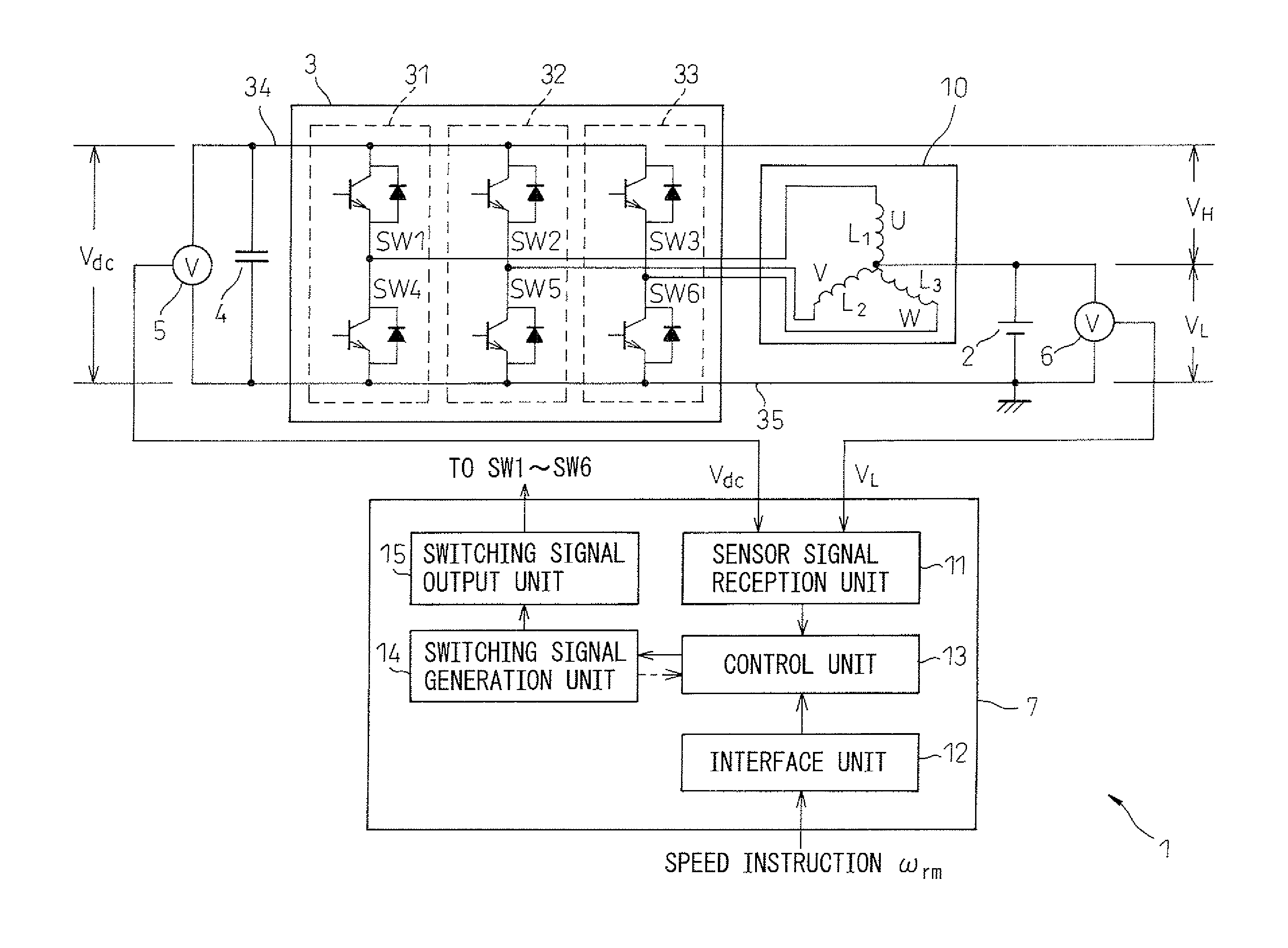
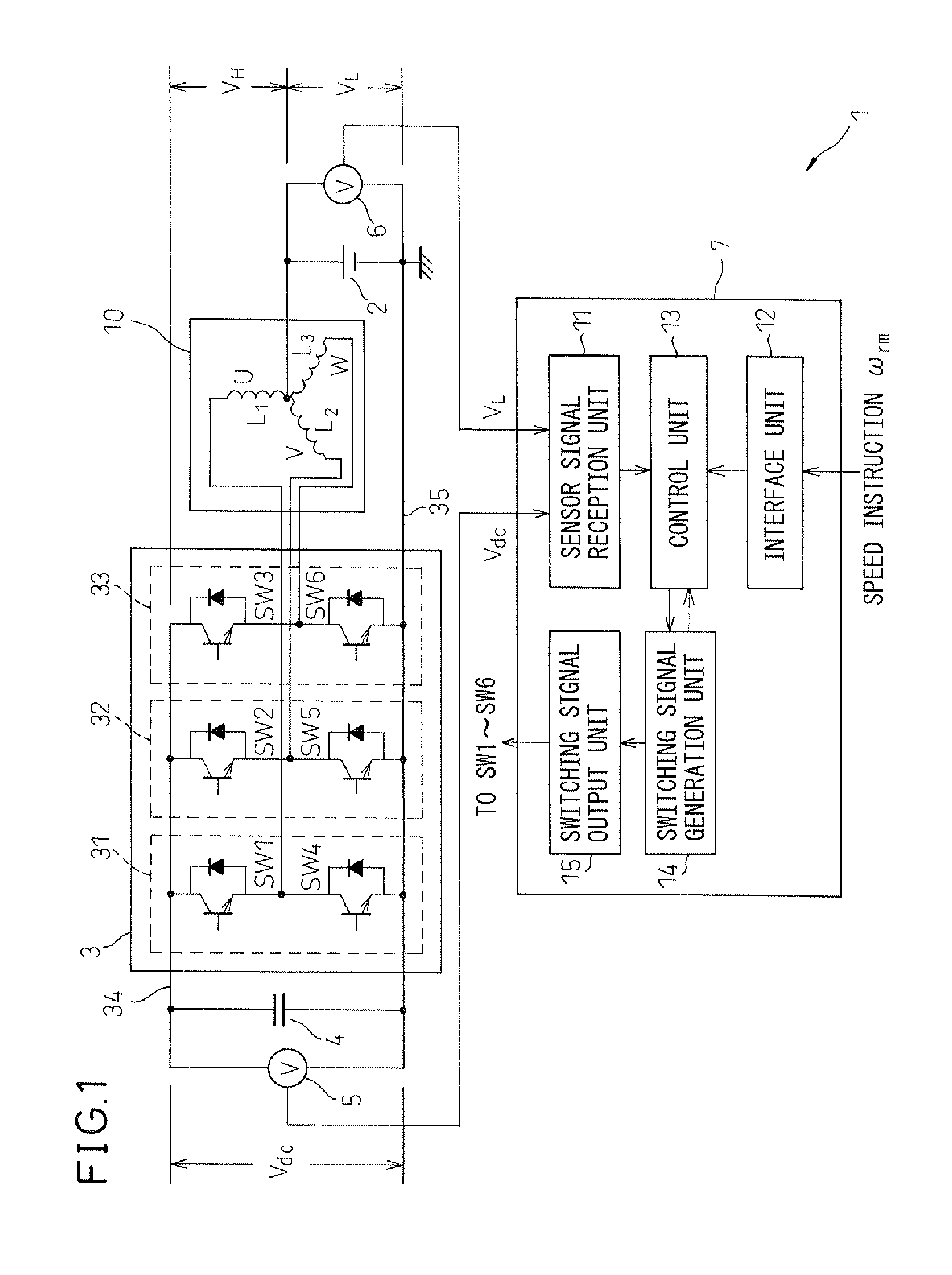
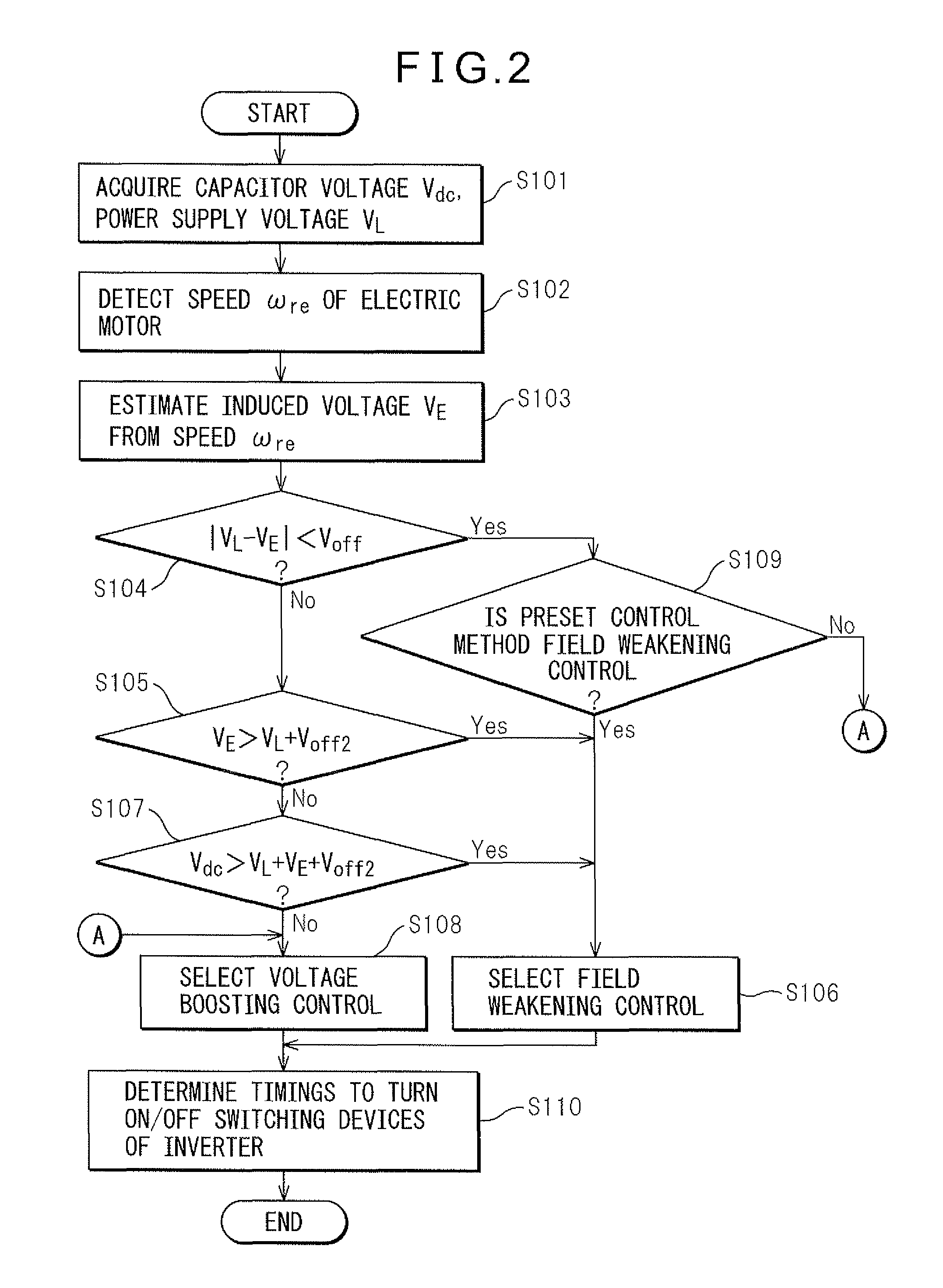
[0024]Below, an electric motor drive device according to a first embodiment of the present invention will be explained. This electric motor drive device drives an AC electric motor having a plurality of coils. The coils are provided at a rotor or stator for giving a drive force to the rotor and generate a rotating magnetic field by the flow of the different phases of current of the three-phase AC. Further, this electric motor drive device uses the results of comparison of a DC voltage supplied between a neutral point where the plurality of coils are connected in a star configuration and a positive rail or negative rail of the inverter and an induced voltage generated at the AC electric motor as the ba...


PUM


Abstract

An electric motor drive device has an inverter adjusting the voltage applied to an AC electric motor so as to drive the AC electric motor, a capacitor which is charged by a current supplied from a DC power supply supplying DC voltage between a neutral point at which a plurality of coils of the AC electric motor are connected and a positive rail or negative rail of an inverter and passing through the inverter, and a control circuit controlling the inverter so that the AC electric motor turns at a designated speed. Further, the control circuit selectively uses field weakening control and voltage boosting control for control of the inverter according to the conditions of the induced voltage generated at the AC electric motor, DC power supply, and voltage of the capacitor.

Description

CROSS-REFERENCE TO RELATED APPLICATION[0001]The applicant claims the right to priority based on Japanese Patent Application No. 2009-183363, filed on Aug. 6, 2009. The entire content of Japanese Patent Application No. 2009-183363 is hereby incorporated by reference.TECHNICAL FIELD[0002]The present invention relates to an electric motor drive device controlling an electric motor driven by multi-phase AC electric power, a control method of an electric motor drive device, and an electrically driven device in which such an electric motor drive device is assembled.BACKGROUND ART[0003]In the past, the art has been developed of using an inverter to convert DC electric power to three-phase AC electric power and using that three-phase AC electric power to drive an AC electric motor. As one example of the drive method of an electric motor using this art, “field weakening control” weakening the magnetic field which a field system generates so as to lower the induced voltage generated in an ele...

Claims


Application Information

Patent Timeline
Patent Type & Authority Patents(United States)
IPC IPC(8): H02P6/00H02M3/155H02M7/48H02M7/5387H02P21/00H02P21/02H02P21/14H02P21/18H02P21/24H02P21/28H02P23/02H02P23/07H02P23/14H02P23/28H02P27/06H02P27/08
CPCH02P27/08H02P23/0068H02P23/22
Inventor SAKAI, KOJIYAMANAKA, AKITOMO
Owner DENSO CORP
Learn More