Aircraft bird strike avoidance method and apparatus using transponder

a technology of aircraft and transmitter, applied in the field of aircraft bird strike avoidance methods and apparatus using transponders, can solve the problems of difficult addition of additional antennas and transmitters to aircraft, and achieve the effect of maximizing the transmit antenna and receiving antenna isolation

Inactive Publication Date: 2012-10-02
PIESINGER GREGORY HUBERT
View PDF4 Cites 27 Cited by
  • Summary
  • Abstract
  • Description
  • Claims
  • Application Information

AI Technical Summary

Benefits of technology

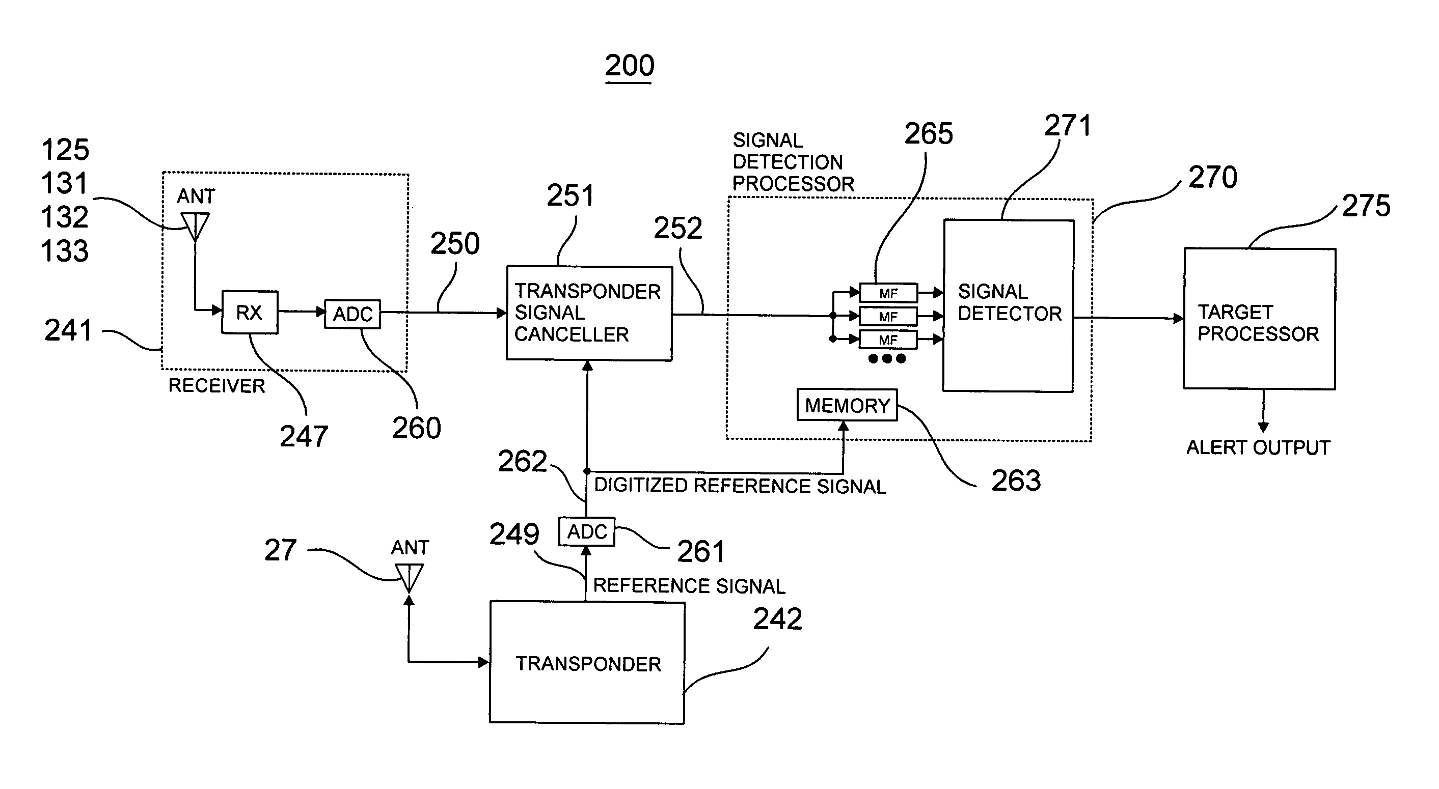
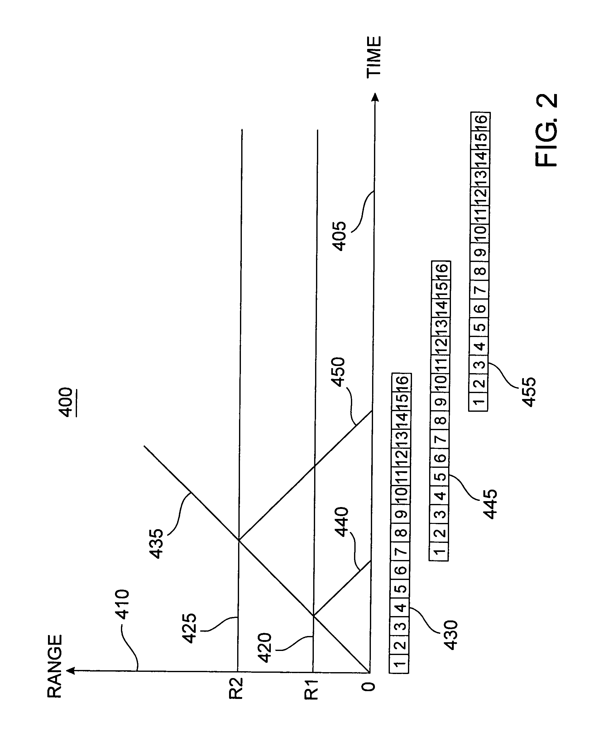
[0008]It is always difficult to add additional antennas and transmitters to aircraft. To reduce the difficulty of adding avian radar to an aircraft, the present invention describes how an existing aircraft transponder and its transmit signal can be used as part of an avian radar system. Briefly, to achieve the desired object of the present invention, the ending period of a standard transponder transmission signal is digitized, saved, and cross correlated with the ending period of reflected avian target signals. Only the ending signal period is used to avoid self jamming of the low level reflected received signal by the active transmission signal. That is, the reflected signal is ignored until the transmission signal is completed.
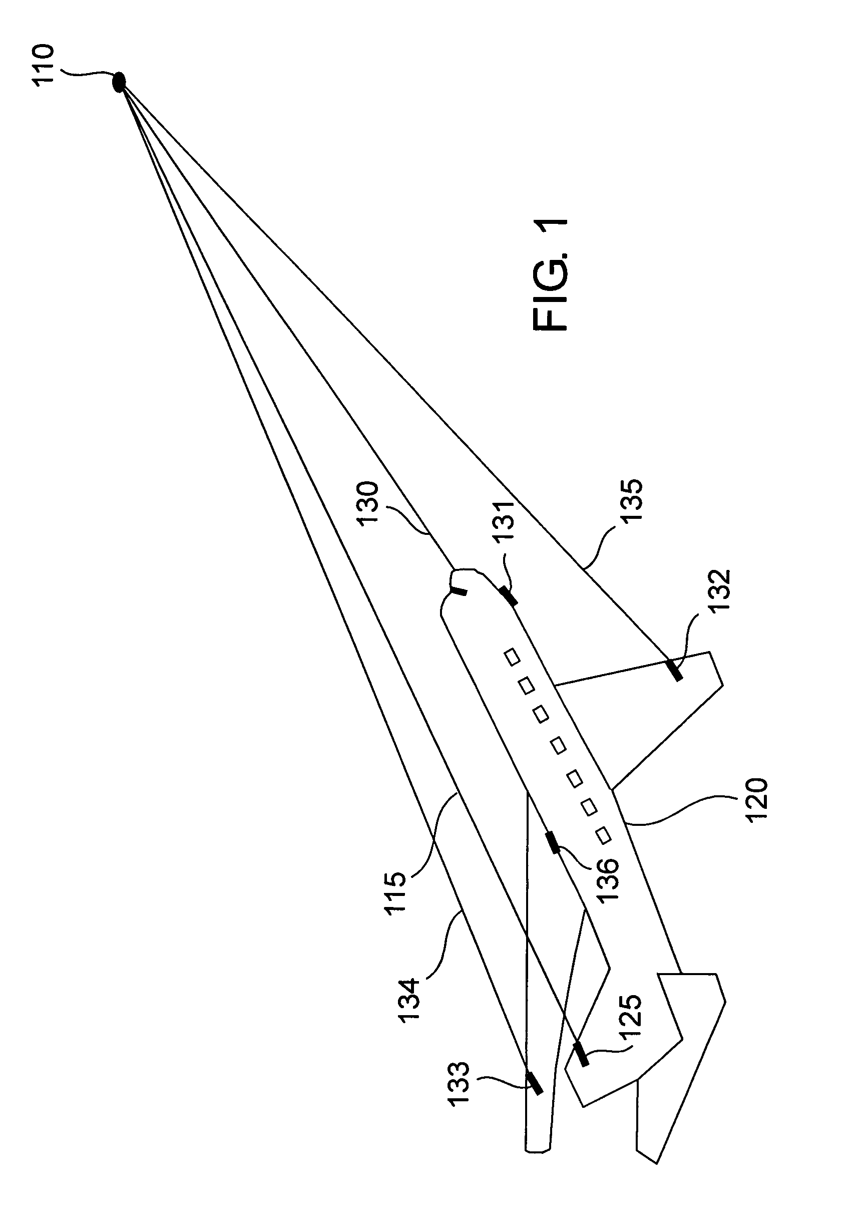
[0009]In a first implementation, the current transponder antenna is used for both transmission and reception. In a second implementation, an external receive only antenna is mounted in a position that maximizes the transmit antenna to receive antenna isolation. This allows more of the ending period of the transmit signal to be cross correlated with the reflected target signal without being jammed by the transmit signal. In a third implementation, a signal canceller and sample of the transmit signal are used to cancel or null out as much transmit signal as possible that couples to the receive antenna. This allows even more, or possibly all, of the transmit signal to be used without jamming the receive signal.

Problems solved by technology

It is always difficult to add additional antennas and transmitters to aircraft.

Method used


Image

  • Aircraft bird strike avoidance method and apparatus using transponder
  • Aircraft bird strike avoidance method and apparatus using transponder
  • Aircraft bird strike avoidance method and apparatus using transponder

Examples


Embodiment Construction

[0020]Secondary Surveillance Radar (SSR) is ground based radar used by Air Traffic Control (ATC) to track airborne aircraft. When an aircraft is illuminated by this radar, a transponder aboard the aircraft sends back a coded signal which appears on the ground radar display. In the USA, this system is known as the Air Traffic Control Radar Beacon System (ATCRBS) and relies on the aircraft transponder which receives interrogations from the SSR on one frequency and responds on another frequency.

[0021]When the transponder receives a radar signal it sends back a transponder code. Early transponders were called Mode A and were later upgraded to Mode C which provided pressure altitude information. Modern transponders are called Mode S and are designed to help avoid over interrogation of the transponder, for the Traffic alert and Collision Avoidance System (TCAS), and to provide Automatic Dependent Surveillance Broadcasts (ADS-B).

[0022]The transmission frequency of transponders is 1090 MHz ...


PUM


Abstract

An aircraft avian radar is implemented using an existing aircraft transponder, Mode S, or TCAS installation as the radar transmitter. To eliminate self jamming of low level avian target signals by high level transmitter signals, the ending period of the transmission signal is digitized and cross correlated with the ending period of reflected avian target signals received after the transmission signal has ended. In a first implementation, the current transponder antenna is used for both transmission and reception. In a second implementation, an external receive only antenna is mounted in a position that maximizes the transmit antenna to receive antenna isolation. In a third implementation, a signal canceller and sample of the transmit signal are used to cancel or null out as much transmit signal as possible that couples directly to the receive antenna.

Description

RELATED INVENTION[0001]The present invention claims priority under 35 U.S.C. §119(e) to: “Aircraft Bird Strike Avoidance Method and Apparatus using Transponder or Pseudolites” Provisional U.S. Patent Application Ser. No. 61 / 211 / 409, filed 30 Mar. 2009, which is incorporated by reference herein.TECHNICAL FIELD OF THE INVENTION[0002]The present invention relates to the detection and avoidance of imminent aircraft collisions with birds or other airborne hazards such as other aircraft.BACKGROUND OF THE INVENTION[0003]Aviation experts say bird-plane collisions happen daily. Nearly 200 people have been killed or injured since 1990 in accidents involving aircraft and wildlife. It is estimated that bird strikes cost military and commercial aviation over $2 billion each year due to damage and other costs. Most birds fly below 5,000 ft. However, bird strikes have occurred at 17,000 ft. and a few sightings have been made above 20,000 ft. In general, birds fly higher at night and during the spr...

Claims


Application Information

Patent Timeline
Patent Type & Authority Patents(United States)
IPC IPC(8): G01S13/74
CPCG01S7/412G01S13/003G01S13/878G01S13/9303G01S13/781G01S13/933
Inventor PIESINGER, GREGORY HUBERT
Owner PIESINGER GREGORY HUBERT
Why Eureka
Try Eureka