
Retractable awning

a technology of awnings and awnings, which is applied in the field of retractable coverings, can solve the problems of reducing the service life of awnings, so as to increase the need for tension, increase the transverse tension, and increase the screen tension

Inactive Publication Date: 2012-10-09
CUTLER
View PDF22 Cites 8 Cited by
  • Summary
  • Abstract
  • Description
  • Claims
  • Application Information

AI Technical Summary

Benefits of technology

"The invention is a retractable covering apparatus for a screen, such as an awning or canopy. The apparatus includes a screen that can be extended and retracted using a first motor and a second motor. The first motor extends the screen and the second motor retracts the screen. The motors are controlled by a control unit that ensures the screen is always tensioned and prevents sagging or creasing during extension and retraction. The control unit can be a conventional awning controller or a control system comprising a main control unit and local master / slave control units. The invention allows for easy and synchronized control of the screen, ensuring it is always in the correct position and tensioned."

Problems solved by technology

A major problem with all of these types of covering is providing sufficient tension in the screen so that the canopy does not sway unduly or flap in the wind.
However, the limit of tension which can be provided by springs is fairly low and varies with the length of the screen which has been extended.
Also, springs lose their elasticity over time or if they are extended too far.
This limit of tension has been a major factor in limiting the size (both width and length) of such covering systems.
Thus tension can be readily applied to the screen, and is limited only by the strength of the clamping system, the wires and the screen itself as opposed to springs as in the prior art.
However, the clamping systems will be subject to external forces such as wind, and other obstacles to movement such as debris on the tensile wires.
Furthermore, the clamping systems can slip along wires (e.g. if they are wet or greasy), again, in a non-equal fashion.
Also the motors may provide different drive forces, for example due to manufacturing tolerances or, variations in the power supply may cause one motor to pull momentarily stronger or to suffer a lull.
This can cause unbalanced pulling forces to be applied to the screen which can consequently be deployed and retracted in a lopsided fashion.
Not only does this make the screen less effective, but it can damage the screen.
These drawbacks will be particularly pronounced with larger screens where the clamping units have to travel greater distances and support heavier weights.
Where a large canopy is involved, a significant retraction force is required which can be difficult to provide.
When retracting the screen with unbalanced forces at either side of the screen, there is a further problem; with the unequal forces, the screen can become skewed and as it is retracted onto the storage roller, the screen may not roll up straight.
Also uneven pulling can lead to wrinkles forming in the screen.
As these wrinkles are wound onto the screen, they become folds and creases in the fabric.
Such wrinkles and creases create weaknesses in the fabric of the screen.
Under the high tensions involved in such canopies, there is a greatly increased chance of the fabric tearing at such weaknesses.
Once the screen has been deployed, even when the clamps are clamped in place, external forces such as wind can still cause them to move, thus resulting in a loss in tension or an uneven tension in the screen.
As the screen is raised significantly above the ground, wind passes both over and underneath the screen and the screen can easily catch the wind and experience high forces.

Method used


Image

  • Retractable awning
  • Retractable awning
  • Retractable awning

Examples


Embodiment Construction

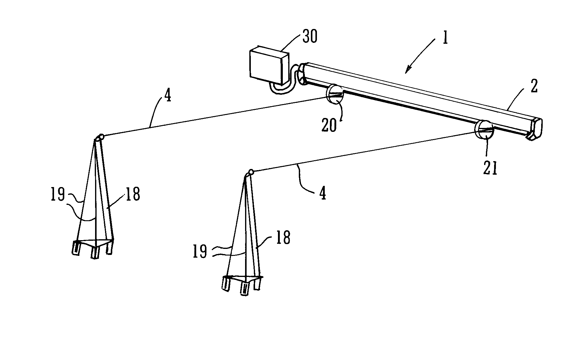
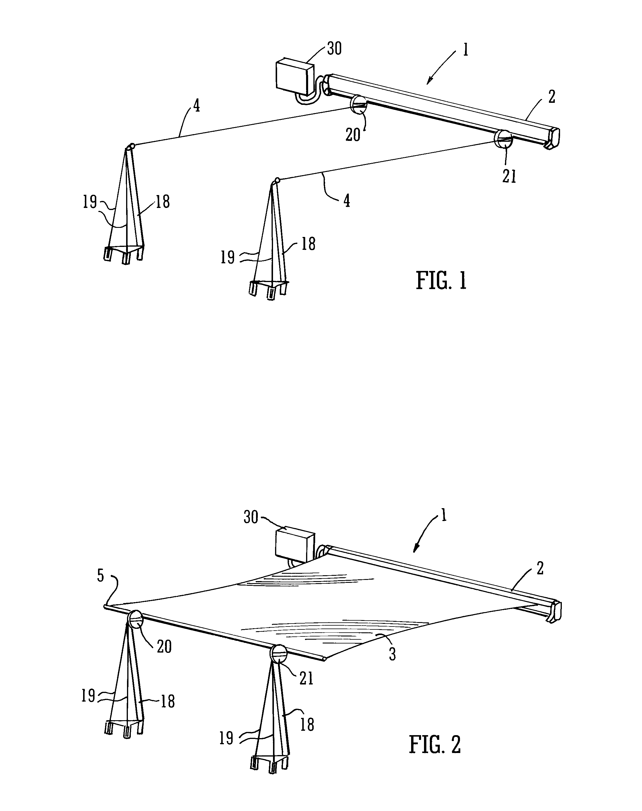
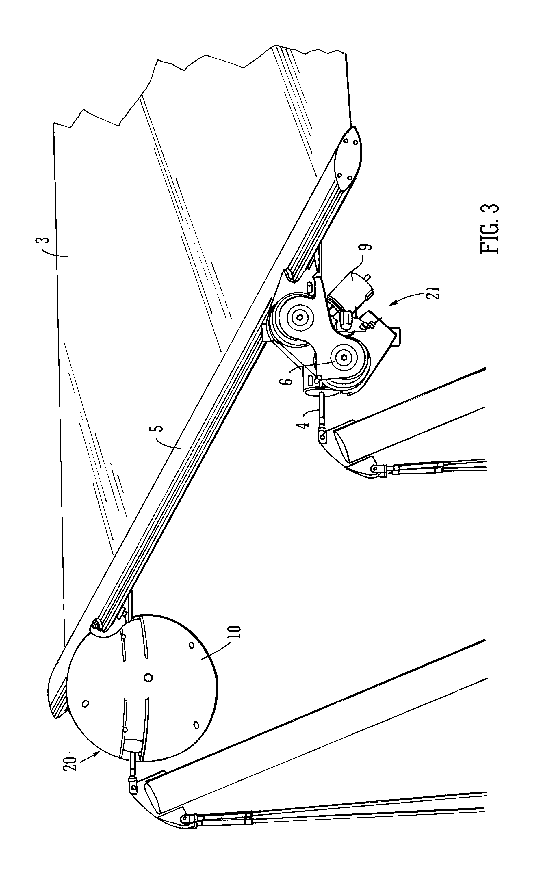
[0054]FIGS. 1 and 2 illustrate a covering apparatus 1 in closed and open positions respectively. The covering apparatus 1 comprises a storage roller 2 at the trailing end of a screen 3. Any portion of the screen which is not deployed is rolled up on the storage roller 2 which typically takes the form of a cylindrical shaft and is typically housed in a housing. Two cables 4 which are under high tension are provided to support the deployed screen and prevent it sagging too much under its own weight. The storage roller 2 and cable ends are attached to a wall. The other end of each cable 4 is attached to a supporting pole 18 which is anchored to the ground using guy wires 19. The support pole 18 is typically embedded in the ground and is angled slightly away from the vertical in a direction substantially opposite to that in which tension is to be applied. This allows the pole 18 to withstand a greater force.

[0055]As shown in more detail in FIG. 3, at the leading edge of the screen 3 a t...


PUM


Abstract

A retractable awning, comprising a screen which may be extended and retracted, wherein there is provided a first motor arranged to extend the screen, a second motor arranged to retract the screen, and a control unit arranged to control the first and second motors, wherein the first and second motors are synchronized so as to maintain tension in the screen within predetermined values.

Description

TECHNICAL FIELD[0001]The present invention relates to a retractable covering apparatus such as a canopy or awning, having a control unit for controlling the extension and retraction thereof. The invention also extends to a control system for such an apparatus, and a method for operating a covering apparatus.BACKGROUND OF THE INVENTION[0002]Awnings or canopies are often used for example outside restaurants or in private gardens to cover open areas and provide shelter for the people underneath them, thereby providing sun protection, rain protection or the like. A variety of covering apparatuses are known in the art. For example some canopies are provided on the side of a building, with folding arms which can be extended out from the building when the canopy is to be deployed. Other covering systems have a covering screen attached to moveable wires that are operated to extend or retract the screen.[0003]It is desirable for canopies and awnings to be easily extended and retracted, whils...

Claims


Application Information

Patent Timeline
Patent Type & Authority Patents(United States)
IPC IPC(8): E04H15/58E04F10/06
CPCA01G9/227E04F10/0681E04F10/0644E04F10/0607Y02A40/25A63C19/12E04F10/06A01G9/22
Inventor CUTLER
Owner CUTLER
Learn More