
Rear suspension for a motor vehicle

a rear suspension and motor vehicle technology, applied in the direction of pivoted suspension arms, axle units, transportation and packaging, etc., can solve the problems of time-consuming and expensive manufacturing of suspensions, and achieve the effect of reducing the manufacturing cost of suspensions, reducing the time for assembling, and facilitating welding operations

Inactive Publication Date: 2012-10-09
SISTEMI SOSPENSIONI SPA
View PDF32 Cites 1 Cited by
  • Summary
  • Abstract
  • Description
  • Claims
  • Application Information

AI Technical Summary

Benefits of technology

[0003]It is therefore an object of the present invention to provide a rear suspension for a motor vehicle which can be manufactured in a shorter time and at a lower cost than the prior art. A further object of the invention is to provide a rear suspension for a motor vehicle which can be easily adapted to different models of motor vehicles.
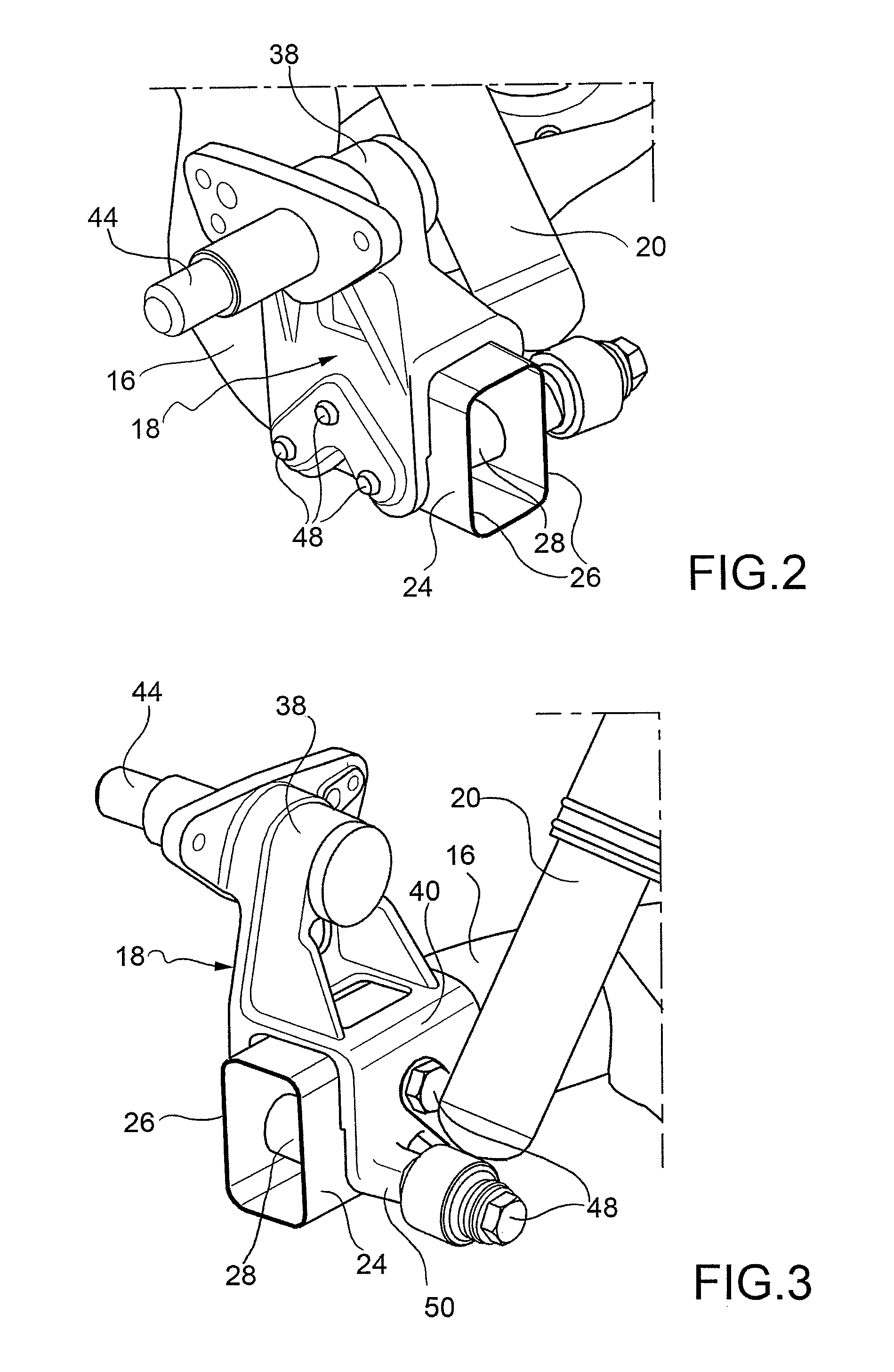
[0009]By virtue of the use of a wheel-carrying structure according to the invention, the welding operations required for manufacturing the suspension become easier, since there is a smaller number of components to be welded and therefore of welding beads to be made. Moreover, the time for assembling the suspension is reduced, since less screw-fixing operations have to be carried out than in the prior art. Finally, by virtue of the use of spacing members which provide the reference and abutment surfaces for the vertical flat walls of the wheel-carrying structure, a precise shape mating between the wheel-carrying structure and the arm length onto which the structure is to be mounted is no more required. Accordingly, the same wheel-carrying structure can be mounted onto arms of different shapes and sizes, which allows a further reduction in the manufacturing costs of the suspension.

Problems solved by technology

The manufacturing of the suspension is therefore time consuming and expensive.

Method used


Image

  • Rear suspension for a motor vehicle
  • Rear suspension for a motor vehicle
  • Rear suspension for a motor vehicle

Examples


Embodiment Construction

[0015]In the description and the claims which follow, terms such as “longitudinal” and “transverse”, “inner” and “outer”, “front” and “rear”, “horizontal” and “vertical” are to be intended as referred to the mounted condition on the vehicle.

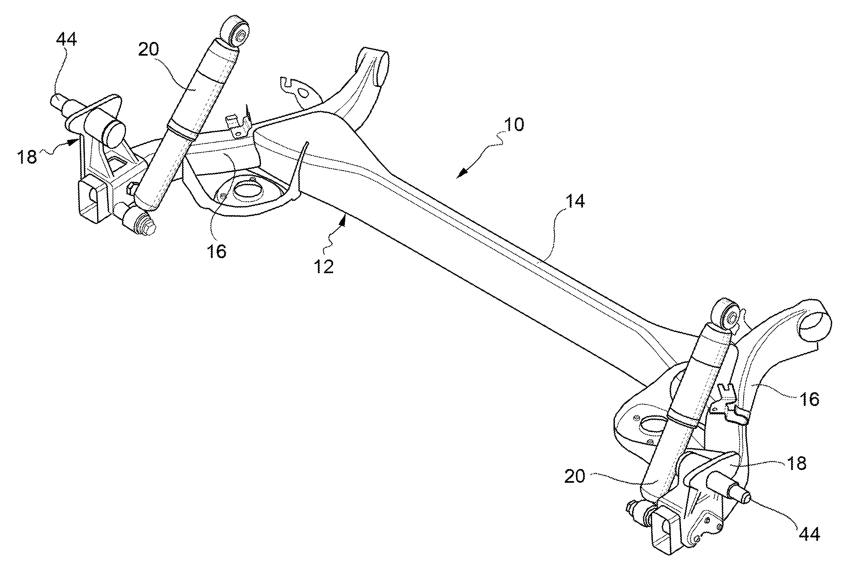
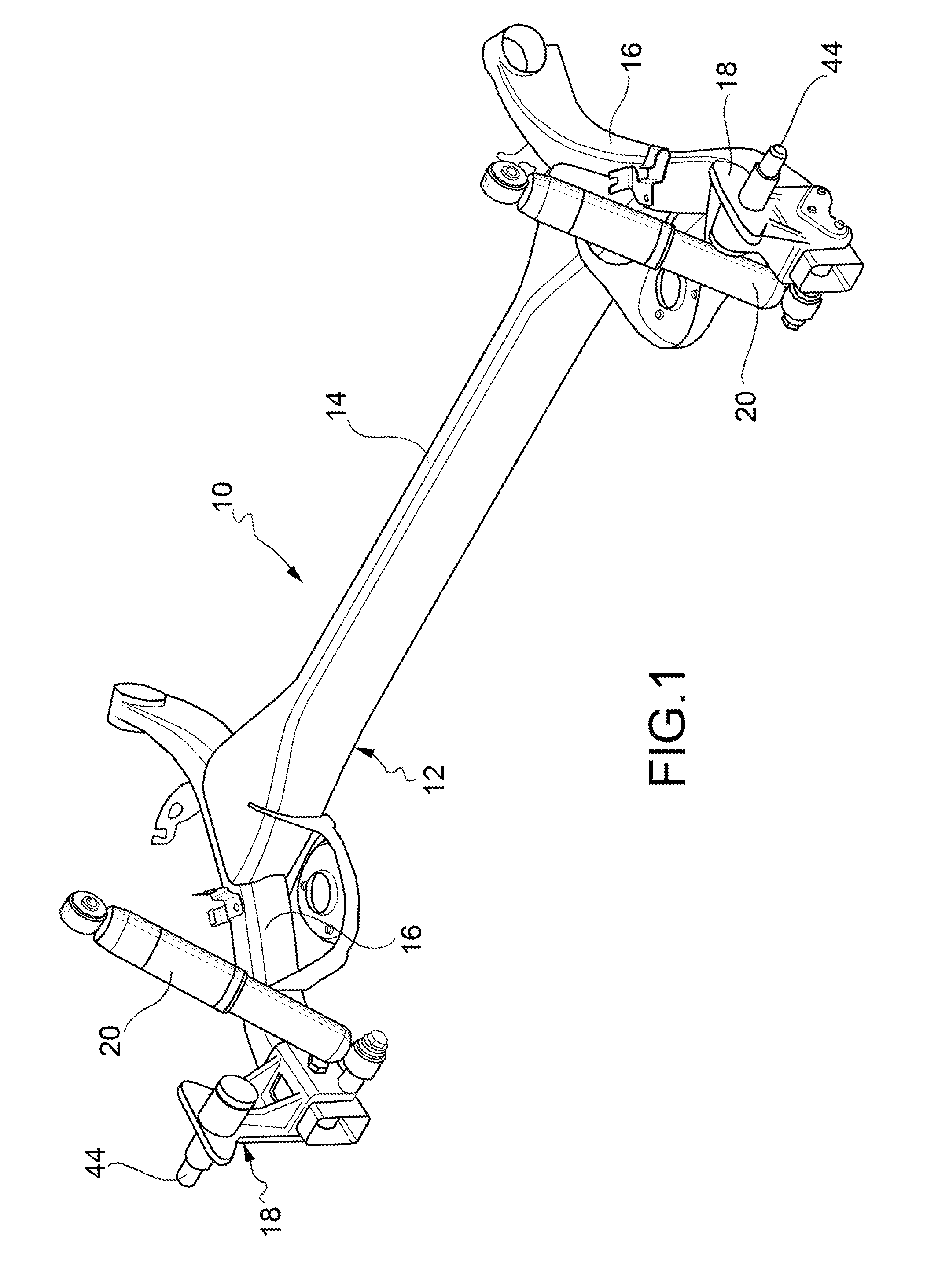
[0016]With reference first to FIG. 1, a rear suspension for a motor vehicle according to the invention, which is made in this case as an interconnected suspension, is generally indicated 10. However, the present invention is not to be considered as limited to this type of suspension, since it can be applied to an independent suspension as well.

[0017]The rear suspension 10 comprises a twist-beam axle 12, which includes in per-se-known manner a cross member 14 and a pair of trailing arms 16, to each of which a wheel-carrying structure 18 is fixed for support of a respective rear wheel (not illustrated). A pair of shock-absorbers 20 and a pair of springs (not illustrated), of per-se-known type, are interposed between the twist-beam axle 12 and the v...


PUM


Abstract

The suspension comprises, for each rear wheel, a trailing arm (16), a wheel-carrying structure (18) fixed to a length (24) of the trailing arm (16) and an axle (44) fixed to the wheel-carrying structure (18). The wheel-carrying structure (18) is made as a single piece forming an upper support portion (38) having a seat (42) into which the wheel axle (44) is inserted and fixed, and a lower attachment portion (40) including a pair of vertical flat walls (34) which are parallel to each other, are arranged astride of said arm length (24) and have a plurality of through holes (46) aligned in pairs. The arm length (24) forms a pair of vertical walls (26) to which three spacers, each having a through hole (30), are fixed, and a pair of end flat surfaces (32). The spacers (28) project beyond the vertical walls (26) of the arm length (24) in such a manner that their end flat surfaces (32) form two abutment flat surfaces for the vertical flat walls (34) of the wheel-carrying structure (18). The wheel-carrying structure (18) is fixed to the arm length (24) by means of three fixing screws (48) inserted into the through holes (46, 30) of the vertical flat walls (34) of the wheel-carrying structure (18) and of the spacers (28).

Description

FIELD OF THE INVENTION[0001]The present invention relates in general to a rear suspension for a motor vehicle, and more in particular to a wheel-carrying structure intended for fixing the axle of a rear wheel to a trailing arm of the suspension.SUMMARY OF THE INVENTION[0002]The solution traditionally adopted to fix the axle of a rear wheel to an arm of the suspension of that wheel, for example a trailing arm of a twist-beam axle, consists in providing a sheet metal support structure which is welded onto the suspension arm and to which the wheel axle is fixed, usually by means of screws. The shock-absorber associated to that wheel is connected to the suspension arm independently of the support structure, usually by means of brackets or threaded spacers. Such a known solution thus requires both a welding operation and a screw-fixing operation. The manufacturing of the suspension is therefore time consuming and expensive.[0003]It is therefore an object of the present invention to provi...

Claims


Application Information

Patent Timeline
Patent Type & Authority Patents(United States)
IPC IPC(8): B60G7/00B60G3/14
CPCB60G7/008B60G21/051B60G2200/13B60G2200/21B60G2200/23B60G2206/8101B60G2204/43B60G2206/10B60G2206/20B60G2206/50B60G2204/129
Inventor BORGI, GUIDO
Owner SISTEMI SOSPENSIONI SPA
Learn More