Vehicle seat slide device

a technology for lowering devices and vehicles, which is applied in the direction of machine supports, movable seats, roofs, etc., can solve the problems of troublesome installment of stopper brackets, limited movement range of upper rail relative to lower rails, etc., and achieve the reduction of the required strength of the movement limiting portion (the first stopper) and the simplified structure of the movement limiting portion

Active Publication Date: 2012-10-09
TOYOTA BOSHOKU KK
View PDF25 Cites 9 Cited by
  • Summary
  • Abstract
  • Description
  • Claims
  • Application Information

AI Technical Summary

Benefits of technology

[0009]Since the insertion hole is formed at an arbitrary position of the first rail in the longitudinal direction, the above described configuration adds to the flexibility of settings of the range of relative movement of the rails. Further, since the first stopper can be attached from the outside of the first rail, the first stopper is easily installed without being interfered by the second rail even when the first stopper is assembled to the first rail after the first and second rails are installed.
[0011]When the movement limiting portion is engaged with the second stopper, a moment is generated in the movement limiting portion, which moment acts to rotate, toward the wall portion, a portion of the movement limiting portion on a side opposite to the second stopper. However, the moment is borne by contact between the portion of the movement limiting portion on a side opposite to the second stopper and the inner surface of the wall portion of the first rail. This allows the movement limiting portion to reliably bear the load generated by the engagement with the second stopper in a shearing direction. Thus, the strength of the first stopper is sufficiently increased by a simple structure.
[0015]According to this configuration, the plate-like attachment portion reduces the projecting amount of the attachment portion in relation to the first rail. Also, since the attachment portion and the flanges are formed by bending a plate, the first stopper having a simple structure can be formed easily.
[0017]According to this configuration, when the flanges and the second stopper are engaged with each other, a moment is generated in the flanges, which moment acts to rotate a portion on a side contacting the second stopper in a direction away from the wall portion. However, the moment is borne by contact between the extended piece and the outer surface of the wall portion of the first rail. Therefore, the flanges are capable of more reliably bearing the load generated by the engagement with the second stopper in a shearing direction.
[0019]According to this configuration, when the flanges and the second stopper are engaged with each other, the extended piece is pressed against the outer surface of the wall portion of the first rail. Therefore, the fastening member does not bear the load in a tensile direction. Thus, the required strength of the fastening member is reduced, which allows the structure of the fastening member to be simplified.
[0021]According to this configuration, the load generated by the engagement between the movement limiting portion and the second stopper is borne by both of the movement limiting portion and the existing portion in a dispersed manner. Thus, the required strength of the movement limiting portion (the first stopper) is reduced, which allows the structure of the movement limiting portion to be simplified.

Problems solved by technology

The movement range of the upper rail relative to the lower rail is limited by causing the stopper bracket to contact the pin.
However, since the stopper bracket needs to be attached from the inside of the upper rail, which has a substantially U-shaped cross section, the installment of the stopper bracket is troublesome.

Method used


Image

  • Vehicle seat slide device
  • Vehicle seat slide device
  • Vehicle seat slide device

Examples


first embodiment

[0043]the present invention will now be described with reference to the drawings.

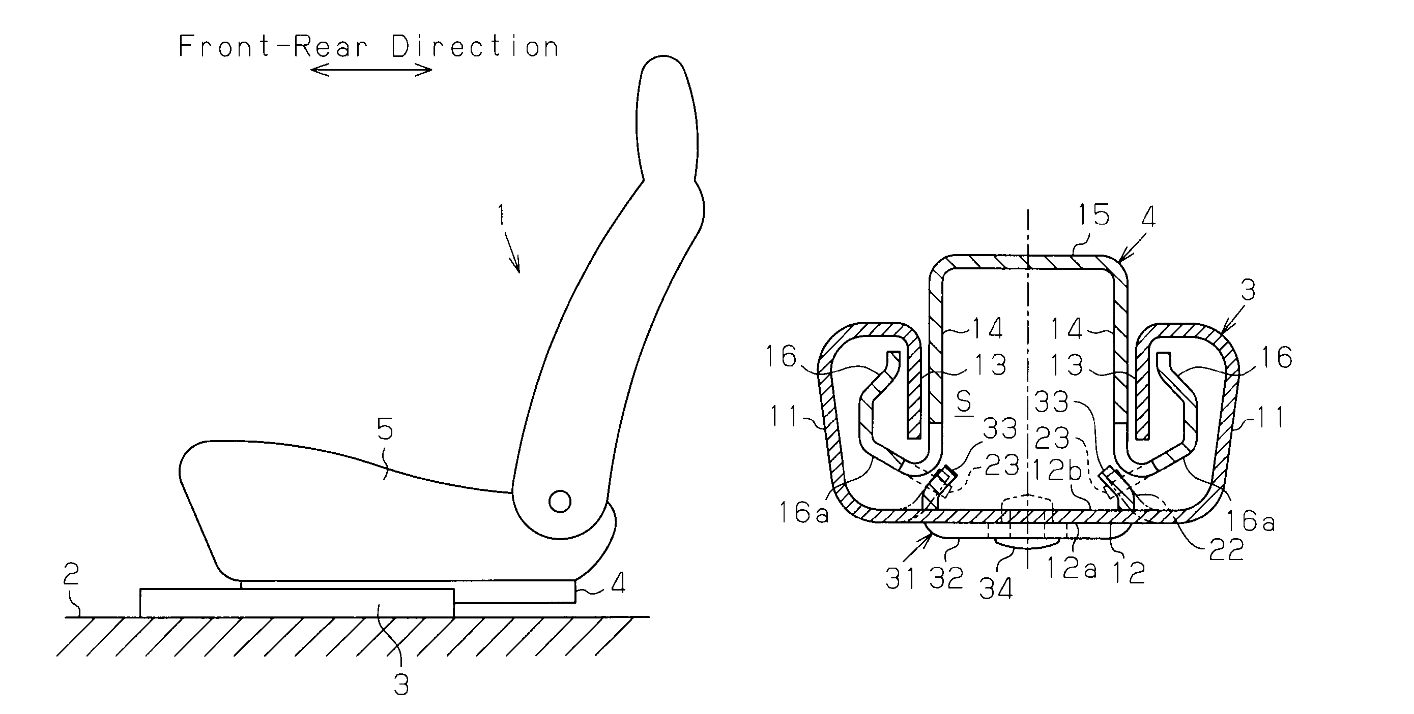
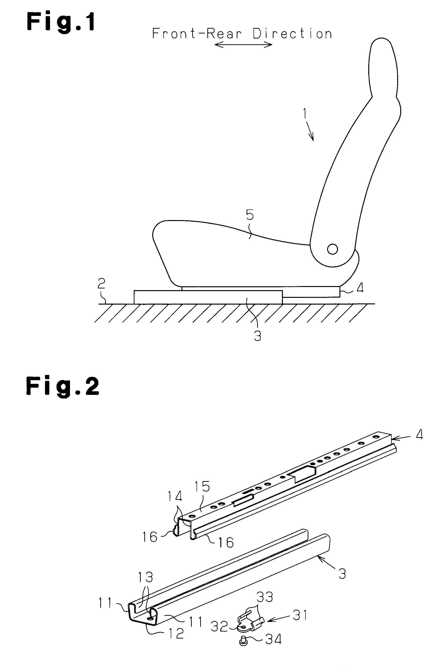
[0044]FIG. 1 schematically shows a vehicle seat 1, which is mounted, for example, on a vehicle, and a seat slide device, which slidably supports the seat 1 on a vehicle floor 2. The seat slide device includes a pair of lower rails 3 (only one of them is illustrated) and a pair of upper rails 4 (only one of them is illustrated). The lower rails 3 are fixed to the vehicle floor 2 and extend along the front-rear direction of the vehicle, and the upper rails 4 are fixed to a seat portion 5 of the vehicle seat 1. The upper rails 4 are movably assembled to the lower rails 3.

[0045]The lower rails 3 are arranged in parallel to each other and spaced at a predetermined interval along the widthwise direction of the vehicle seat 1 (the direction perpendicular to the elevation of FIG. 1). Likewise, the upper rails 4 are arranged in parallel to each other and spaced at a predetermined interval along the widthwise dir...

third embodiment

[0087]In the present embodiment, a stopper 71 shown in FIG. 12 is employed as a first stopper. The stopper 71 of the present embodiment is formed by providing the stopper 51 of the third embodiment with a pair of extended pieces 52b, 52c. That is, as shown in FIG. 12, an attachment portion 52 of the stopper 71 includes a flat plate-like coupling piece 52a and the first and second extended pieces 52b, 52c. The first and second extended pieces 52b, 52c are extended beyond the flanges 53 from the front end and the rear end of the coupling piece 52a in a direction of relative movement of the rails 3, 4. The extended pieces 52b, 52c contact the outer surface 12a of the bottom wall portion 12.

[0088]As shown in FIG. 13, the attachment portion 52 is fastened (fixed) to the bottom wall portion 12 of the lower rail 3 by a rivet 54, which serves as fastening means (a fastening member), at the coupling piece 52a, which is a portion between the extended pieces 52b, 52c. Through hole for receivin...

fourth embodiment

[0093]In the present embodiment, a stopper 81 shown in FIG. 14 is employed as a first stopper. The stopper 81 of the present embodiment is different from the stopper 71 of the fourth embodiment in the following points. That is, the attachment portion 52 is fastened (fixed) to the bottom wall portion 12 of the lower rail 3 by rivets 54, which functions as fastening means (a fastening member), at the first and second extended pieces 52b, 52c. Through holes for receiving the rivets 54 are formed in the extended pieces 52b, 52c and the bottom wall portion 12.

[0094]The attachment portion 52 is fitted to the bottom wall portion 12 by a projection / recess fitting structure at the coupling piece 52a, which is a part between the extended pieces 52b, 52c. The projection / recess fitting structure includes a recess 82 formed in the outer surface 12a of the bottom wall portion 12 and a projection 83 formed on the coupling piece 52a to be fitted in the recess 82. As in the fourth embodiment, the pr...


PUM


Abstract

A stopper includes an attachment portion and a pair of flanges. The attachment portion contacts an outer surface of a bottom wall portion of a lower rail and is attached to the bottom wall portion. The flanges extend from the attachment portion to be passed through insertion holes in the bottom wall portion. The flanges are located in an inner space of the lower rail. The flanges are engaged with second cut-and-raised pieces formed in an upper rail, thereby limiting the range of movement of the upper rail relative to the lower rail.

Description

TECHNICAL FIELD[0001]The present invention relates to a vehicle seat slide device.BACKGROUND ART[0002]Conventionally, various types of vehicle seat slide devices have been proposed. For example, a vehicle seat device disclosed in Patent Document 1 includes a pair of lower rails fixed on a vehicle floor and a pair of upper rails fixed to a seat. The upper rails are supported by the lower rail to be movable relative to the lower rails. Each lower rail has a pair of plate-like stoppers at a center portion in the longitudinal direction. The stoppers are formed by cutting and raising parts of the bottom wall portion of the lower rail. On the other hand, each upper rail has a pair of plate-like stoppers at either end in the longitudinal direction. The stoppers are formed by cutting and raising parts of the vertical wall portions of the upper rail. The stoppers at each end of the upper rails can contact and be engaged with the stoppers of the lower rails along the moving direction of the u...

Claims


Application Information

Patent Timeline
Patent Type & Authority Patents(United States)
IPC IPC(8): B60N2/07B60N2/90
CPCB60N2/0727
Inventor KOJIMA, YASUHIRONIHONMATSU, HIDEOHORI, YOSHIHISA
Owner TOYOTA BOSHOKU KK
Why Eureka
Try Eureka