Crossed roller bearing retainer and crossed roller bearing

a technology of cross-roll bearings and retainers, which is applied in the direction of bearings, shafts and bearings, rotary bearings, etc., can solve the problems of non-trivial production and comparatively high production costs that remain to be resolved

Active Publication Date: 2012-10-09
HARMONIC DRIVE SYST IND CO LTD
View PDF9 Cites 10 Cited by
  • Summary
  • Abstract
  • Description
  • Claims
  • Application Information

AI Technical Summary

Benefits of technology

[0009]With the foregoing aspects of the prior art in view, it is an object of the present invention to provide a crossed roller bearing retainer that has a simple shape and also maintains a fixed spacing between adjacent rollers.
[0010]Another object of the present invention is to provide a crossed roller bearing retainer having a simple shape that provides grease accumulation.
[0015]According to the crossed roller bearing retainer of the present invention, the side surfaces on both sides of the rectangular-profile retainer body plate form slanted flat surfaces, and these slanted flat surfaces extend in the direction of the bearing center. Consequently, the circular external circumferential surfaces of adjacent rollers are in linear contact with each other, and the spacing between them is held constant. In other words, adjacently-disposed rollers can be held at a fixed spacing utilizing a retainer having a simple shape in which the thickness of the rectangular-contoured plate gradually decreases from one corner to the other corner on one of the diagonal lines thereof.
[0016]In addition, as a grease accumulation, recess parts are formed on the slanted flat surfaces on both sides of the rectangular-profile retainer body plate, and these parts are communicated to each other, thereby allowing smooth supply of grease to the rollers in a state of linear contact via the grease accumulation.

Problems solved by technology

There are thus problems with non-trivial production as well as comparatively high production costs that remain to be resolved.

Method used


Image

  • Crossed roller bearing retainer and crossed roller bearing
  • Crossed roller bearing retainer and crossed roller bearing
  • Crossed roller bearing retainer and crossed roller bearing

Examples


Embodiment Construction

[0022]A crossed roller bearing of an embodiment of the present invention is described below with reference to the drawings.

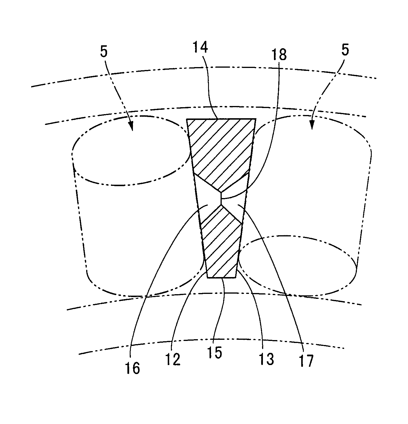
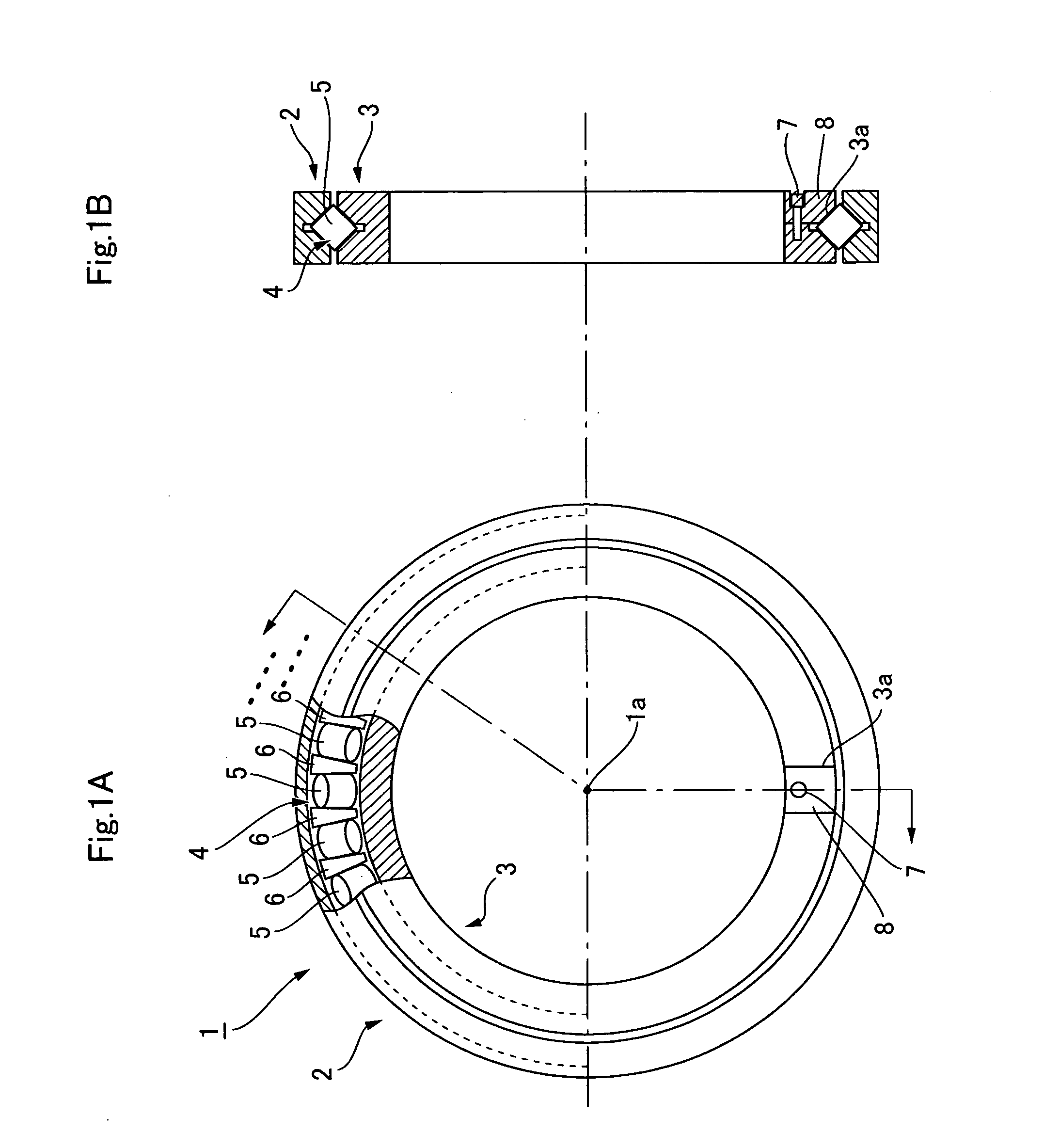
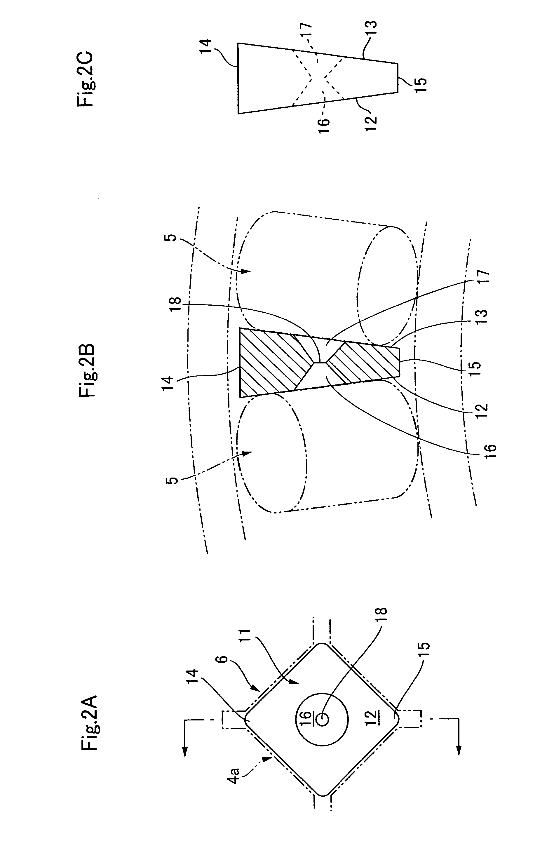
[0023]As shown in FIGS. 1A and 1B, the crossed roller bearing 1 has an integrally-formed outer ring 2, an integrally-formed inner ring 3, a plurality of cylindrical rollers 5 inserted into a ring-shaped race 4 with a rectangular cross-section formed between the rings 2, 3, and a plurality of retainers 6, each maintaining a fixed spacing between adjacent rollers 5. In this embodiment, the inner ring 3 is formed with a roller insertion groove 3a that extends from one of the ring-shaped side surfaces of the inner ring 3 to the race 4, and the roller 5 and retainer 6 are inserted into the race 4 from the roller insertion groove 3a. A plug 8 is inserted into the roller insertion grove 3a and fixedly connected to the inner ring 3 by a fastening bolt 7, so that the roller insertion groove 3a is sealed. Alternatively, the outer ring 2 or the inner ring 3 can be formed a...


PUM


Abstract

A retainer of a crossed roller bearing has a retainer body plate of rectangular profile corresponding to a rectangular cross-section of a race. Rectangular side surfaces on either side of the retainer body plate are inclined planes that slant in a direction of approaching one another from one corner to another corner along a diagonal line of the surfaces, and extend towards a bearing center in a state of having been installed in the race. Recesses for accumulating grease are formed in center portions of the rectangular side surfaces, the recesses communicating via a through-hole. The rectangular side surfaces are in linear contact with the circular external circumferential surfaces of adjacent rollers and hold the rollers at a fixed spacing. There is obtained a retainer for an uncomplicatedly configured crossed roller bearing that allows adjacent rollers to be held at a fixed spacing and is provided with a grease accumulator.

Description

BACKGROUND OF THE INVENTION[0001]1. Field of the Invention[0002]The present invention relates to a crossed roller bearing in which cylindrical rollers are inserted into an annular race of rectangular cross-section so as to be in an alternatingly crossed state. More specifically, the present invention relates to an improvement to a crossed roller bearing retainer in which the rollers are held at a fixed spacing so that adjacent rollers are not in contact.[0003]2. Description of the Related Art[0004]With crossed roller bearings, a spacer retainer is disposed between rollers that are inserted into a race having a rectangular cross-section, thereby holding the rollers at a fixed spacing so that they do not touch. The spacer retainer is provided with a concave surface that is in surface contact with the circular outer circumferential surfaces of the adjacent rollers as disclosed in FIGS. 2 and 5 of Patent Document 1, in FIG. 4 of Patent Document 2, and in Patent Document 3 below.[0005][P...

Claims


Application Information

Patent Timeline
Patent Type & Authority Patents(United States)
IPC IPC(8): F16C19/40
CPCF16C19/362F16C33/37F16C43/06F16C33/6629F16C33/6681F16C33/60F16C33/51F16C33/52
Inventor KANAI, SATORU
Owner HARMONIC DRIVE SYST IND CO LTD
Why Eureka
Try Eureka