Evacuation system for plastics extrusion

a technology of extrusion system and plastics, applied in the field of plastics industry, can solve the problems of direct health hazards, different contaminants, polluting the production environment, etc., and achieve the effect of reducing unwanted interference with the cooling air flow

Active Publication Date: 2012-10-09
FUTURE DESIGN
View PDF7 Cites 0 Cited by
  • Summary
  • Abstract
  • Description
  • Claims
  • Application Information

AI Technical Summary

Benefits of technology

[0015]The inventors of the present application have now surprisingly discovered that the placement of the air intake of an air evacuation unit axially adjacent the extrusion nozzle and axially spaced from any downstream cooling air outlets is important for reducing unwanted interference with the cooling air flow.
[0016]It has further been discovered that even when the evacuation system is axially spaced from any downstream cooling air outlets, the system must include means for equalizing the suction pressure and intake air flow along the intake opening in order to avoid localized pressure differences around the extruded product.
[0027]the evacuating chamber having a radially inwardly directed annular air intake opening, and means in the evacuation chamber for equalizing suction pressure along the air intake opening, wherein the air intake opening is disposed axially between the die orifice and the annular cooling air outlet means so as to face towards an exterior of the tubular bubble as it is being formed, the intake opening being axially spaced from the air ring and positioned adjacent the die orifice for preventing interference of the suction pressure generated at the air intake opening with a cooling air flow generated by the air ring.

Problems solved by technology

Plastic extrusion processes usually produce different contaminants like smoke, solid particles, vapours and plate off.
Those contaminants are a major factor in polluting the production environment.
Some of them are a direct health hazard while others will pollute the product and affect the quality and composition of the final product.
This requires periodic production shut-down, which is economically undesirable.
However, ventilation and the resulting quick air drafts have inherent problems that may effect the production process so that ventilation by no means is an effective solution to air borne contaminants.
Moreover, ventilation is an expensive pollution control method, since large amounts of air need to be replaced and conditioned to comfort level for the operators and the correct ambient temperature for the production process.
Molten polymeric material, upon issue from an extrusion die orifice, is accompanied by undesirable contaminants, such as smoke, odorous fumes and other airborne contaminants resulting from the extrusion process.
Processing aids for the improved processing of the materials extruded also contribute to contamination of the working environment.
Processing aids generally are no longer useful after they are heated and exit the die.
All of these contaminants serve to increase pollution of the atmosphere immediately within the working environment adjacent to the extrusion apparatus and progressively pass into and pollute the surrounding atmosphere within a factory.
Hence, such contaminants present an uncomfortable and possibly unhealthy atmosphere in which to work and may lead to pollution of the product.
It has now been discovered that this placement of the evacuation system intake is disadvantageous.
Interference with the air flow for the air ring may significantly impact the performance of the air ring and may lead to unpredictable variations in the fluidness and of the extruded film and deformation of the extruded film bubble.

Method used


Image

  • Evacuation system for plastics extrusion
  • Evacuation system for plastics extrusion
  • Evacuation system for plastics extrusion

Examples


Embodiment Construction

[0037]Before explaining the present invention in detail, it is to be understood that the invention is not limited to the preferred embodiments contained herein. The invention is capable of other embodiments and of being practiced or carried out in a variety of ways. It is to be understood that the phraseology and terminology employed herein are for the purpose of description and not of limitation.

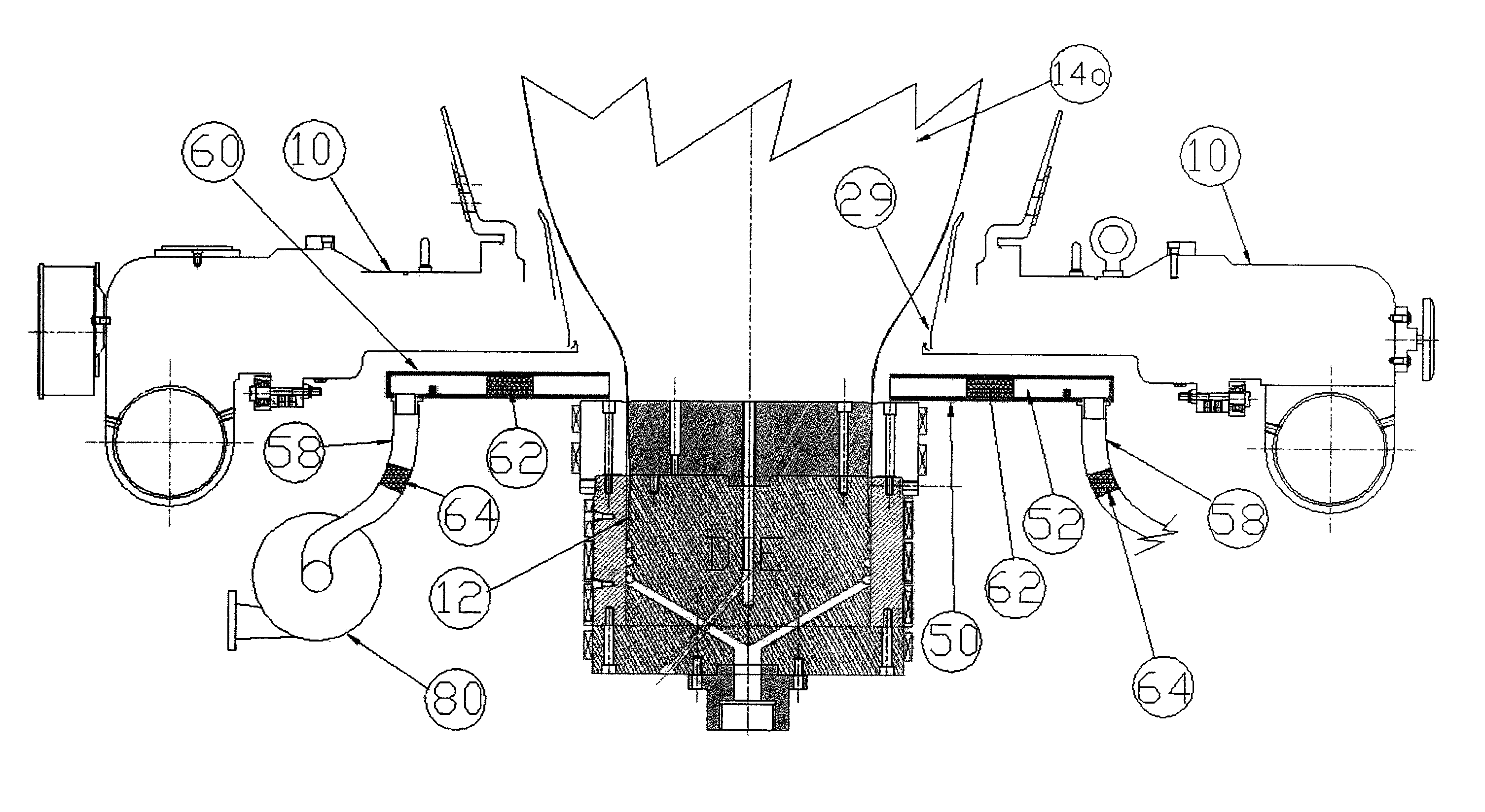
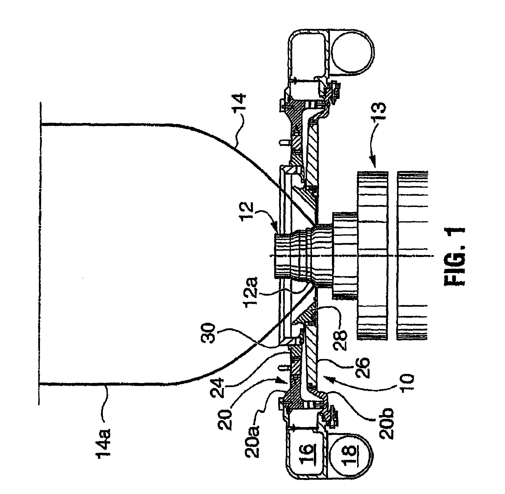
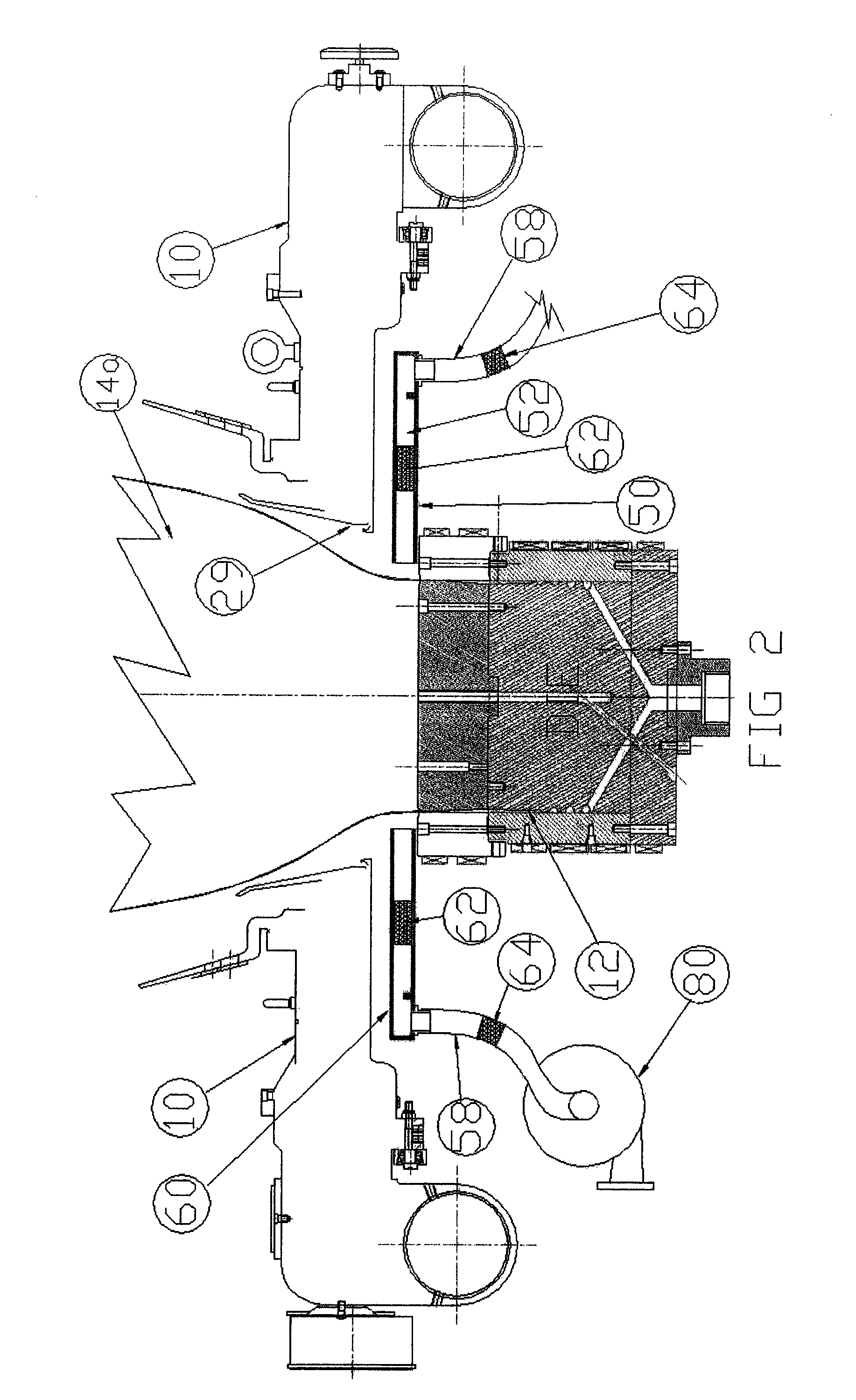
[0038]The invention is directed to plastics extrusion process and apparatus and in particular to contaminant evacuation systems for use therewith.

[0039]While the invention has been described with a certain degree of particularity, it is understood that the invention is not limited to the embodiments set forth herein for purposes of exemplification, but is to be limited only by the scope of the attached claims, including the full range of equivalency to which each element thereof is entitled.

[0040]Although the present invention has been explained hereinabove by way of preferred embodiments t...


PUM

PropertyMeasurementUnit
distanceaaaaaaaaaa
pressureaaaaaaaaaa
vacuum pressureaaaaaaaaaa

Abstract

Disclosed is an evacuation system for use with plastic extrusion dies, in particular a contaminant evacuation system for removal of air borne contaminants generated at the die orifice of a plastics extrusion apparatus. The system includes an annular evacuation chamber and a suction source connected to the evacuation chamber for generating a vacuum in the evacuation chamber. The evacuation chamber has a radially inwardly directed annular air intake opening for placement about the die orifice, and a baffle structure in the evacuation chamber for equalizing suction pressure along the air intake opening and reduce or avoid localized pressure differences around the extruded product, which would lead to deformation of the product.

Description

CROSS REFERENCE TO RELATED APPLICATIONS[0001]This application claims the benefit of priority of U.S. Provisional Patent Application No. 61 / 102,985 filed Oct. 6, 2008, the contents of which is incorporated herein by reference.FIELD OF THE INVENTION[0002]The present invention relates to the plastics industry and in particular to apparatus for plastics extrusion. More particularly, it relates to evacuation systems for use with plastic extrusion dies.BACKGROUND OF THE INVENTION[0003]Plastic extrusion processes usually produce different contaminants like smoke, solid particles, vapours and plate off. Those contaminants are a major factor in polluting the production environment. Some of them are a direct health hazard while others will pollute the product and affect the quality and composition of the final product. Thus, periodic cleaning of the sensitive equipment employed in plastics extrusion processes is required to maintain a clean production environment.[0004]Usually such cleaning t...

Claims


Application Information

Patent Timeline
Patent Type & Authority Patents(United States)
IPC IPC(8): B29C47/20B29C48/32
CPCB29C47/0026B29C47/0877B29C47/8835B29C2791/005B29C48/10B29C48/141B29C48/27B29C48/913
Inventor KRYCKI, ROBERT D.EL-HADDAWI, MOHAMMED
Owner FUTURE DESIGN
Why Eureka
Try Eureka