
Endoscopic imaging using reflection holographic optical element for autostereoscopic 3-D viewing

a technology of autostereoscopic and holographic images, applied in the field of endoscopic imaging, can solve the problems of affecting horizontal resolution and light output, affecting the image quality of the endoscope, so as to improve the color fidelity of the reflected image and the resolution. the effect of high resolution

Active Publication Date: 2012-10-09
ABSOLUTE 3D IMAGING LLC
View PDF333 Cites 18 Cited by
  • Summary
  • Abstract
  • Description
  • Claims
  • Application Information

AI Technical Summary

Benefits of technology

"The patent describes a system and method for creating a three-dimensional image through an endoscope without the need for glasses or headgear. The system includes a stereo endoscope, a reflection holographic optical element, and two projectors that project images onto the hologram. The hologram redirects the light to create two viewing zones that align with the viewer's eyes. The system also includes a head tracking system that synchronizes the movement of the viewer's eyes with the image display to maintain the desired perspective. The use of a reflection holographic element provides higher resolution and improved color fidelity for endoscopic viewing applications. The technical effects of this system include real-time stereo images and viewer position detection and synchronization."

Problems solved by technology

However, glasses or headgear may cause fatigue and / or vertigo in some individuals after extended viewing times due to visual cues from peripheral vision outside the field of view of the glasses or headgear.
However, horizontal resolution and light output are adversely impacted with this approach, and the “sweet spot”, or zone where one can best visualize a stereoscopic image, is very small.
As such, three-dimensional imaging systems based on parallax barriers and Fresnel lenses, as well as those using lenticular sheets, have generally fallen short of user expectations.

Method used


Image

  • Endoscopic imaging using reflection holographic optical element for autostereoscopic 3-D viewing
  • Endoscopic imaging using reflection holographic optical element for autostereoscopic 3-D viewing
  • Endoscopic imaging using reflection holographic optical element for autostereoscopic 3-D viewing

Examples


Embodiment Construction

)

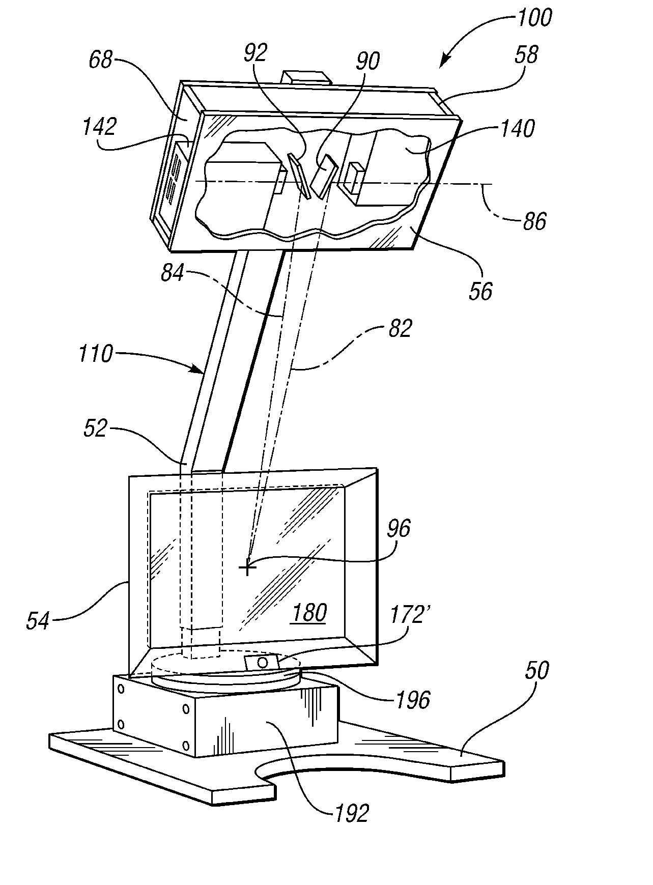
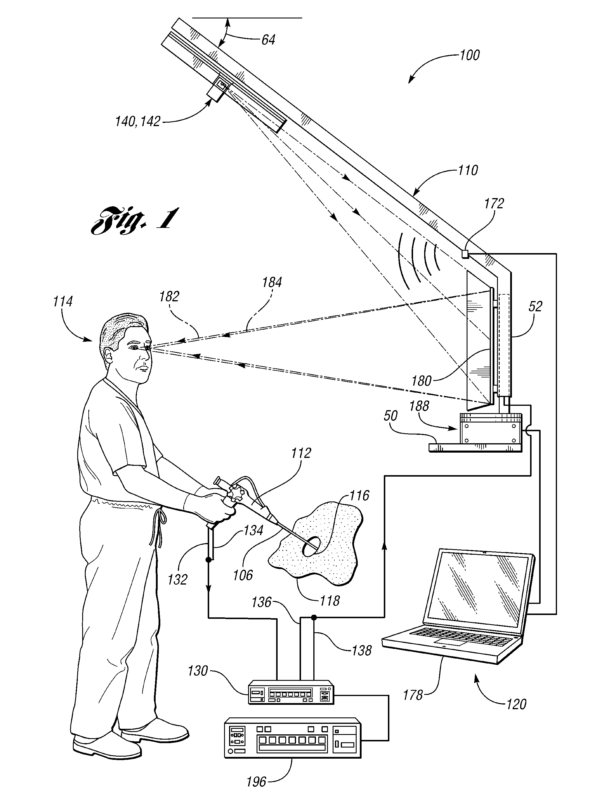
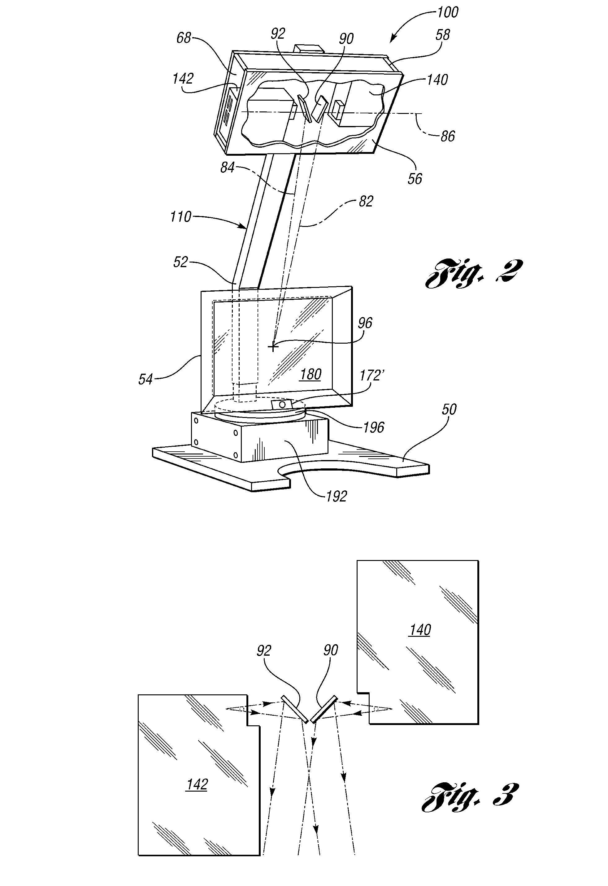
[0021]As those of ordinary skill in the art will understand, various features of the embodiments illustrated and described with reference to any one of the Figures may be combined with features illustrated in one or more other Figures to produce alternative embodiments that are not explicitly illustrated or described. The combinations of features illustrated provide representative embodiments for typical applications. However, various combinations and modifications of the features consistent with the teachings of the present disclosure may be desired for particular applications or implementations. The representative embodiments used in the illustrations relate generally to an autostereoscopic display system and method capable of displaying a stereo image in real-time using either live stereo video input from a stereo endoscope, or a standard video input processed to generate simulated stereo video that is perceived as a three-dimensional image by a properly positioned viewer.

[0022]...


PUM


Abstract

Systems and methods for generating a three-dimensionally perceived image from a stereo endoscope by at least one viewer include an autostereoscopic display having a left projector and a right projector that project corresponding left and right images received from corresponding left and right cameras of the stereo endoscope onto a reflective holographic optical element that redirects light from the left projector to a left viewing zone for a left eye and redirects light from the right projector to a right viewing zone for a right eye of a viewer to create a three-dimensionally perceived image without glasses or optical headgear.

Description

CROSS-REFERENCE TO RELATED APPLICATION[0001]This application is a continuation-in-part of U.S. patent application Ser. No. 12 / 408,447 filed Mar. 20, 2009, the disclosure of which is incorporated by reference in its entirety.BACKGROUND[0002]1. Technical Field[0003]The present disclosure relates to systems and methods for creating and displaying autostereoscopic three-dimensional images from an endoscope using a reflection holographic optical element.[0004]2. Background Art[0005]Sterescopic display devices separate left and right images corresponding to slightly different views or perspectives of a three-dimensional scene or object so that they can be directed to a viewer's left and right eye, respectively. The viewer's visual system then combines the left-eye and right-eye views to perceive a three-dimensional or stereo image. A variety of different strategies have been used over the years to capture or create the left and right views, and to deliver or display them to one or more vi...

Claims


Application Information

Patent Timeline
Patent Type & Authority Patents(United States)
IPC IPC(8): H04N5/89H04N7/00
CPCG02B23/24G02B27/0093G02B27/225
Inventor BJELKHAGEN, HANS INGMARFISCHBACH, JAMES CLEMENT
Owner ABSOLUTE 3D IMAGING LLC
Learn More