Filament lamp

a filament lamp and filament technology, applied in the direction of discharge tube/lamp details, discharge tube/lamp main electrode, incadescent body mounting/support, etc., can solve the problems of non-uniformity and defective products, and achieve the effect of preventing the position of filaments to move and uniform light distribution

Active Publication Date: 2012-10-16
USHIO DENKI KK
View PDF15 Cites 2 Cited by
  • Summary
  • Abstract
  • Description
  • Claims
  • Application Information

AI Technical Summary

Benefits of technology

[0011]In view of the abovementioned problems, the object of the present invention is to provide a filament lamp capable of preventing the position of a filament to move while maintaining a secure insulation of the filament from an internal lead, and maintaining a uniform distribution of light, wherein the filament and the internal lead are disposed inside the luminous tube in parallel with each other in the axial direction of the tube.
[0020]According to the second aspect of the invention, since a pathway is provided along the axis of the tube from one end to the other end between the luminous tube and the insulating wall and the internal lead is provided in the pathway, the pathway positions the internal lead. Accordingly, the disposed position thereof inside the luminous tube does not move. It is therefore possible to avoid the problem that light irradiated from the filament is blocked from an object to be treated arising out of the lopsided movement of the position of an internal lead at the time of turning on or off the lamp.

Problems solved by technology

In other words, a defect caused by crystal transition occurs, which may lead to a defective product.
As a result, there may occur a problem in that the distribution of light generated toward an object to be treated may be changed into a nonuniform pattern.

Method used


Image

  • Filament lamp
  • Filament lamp
  • Filament lamp

Examples


first embodiment

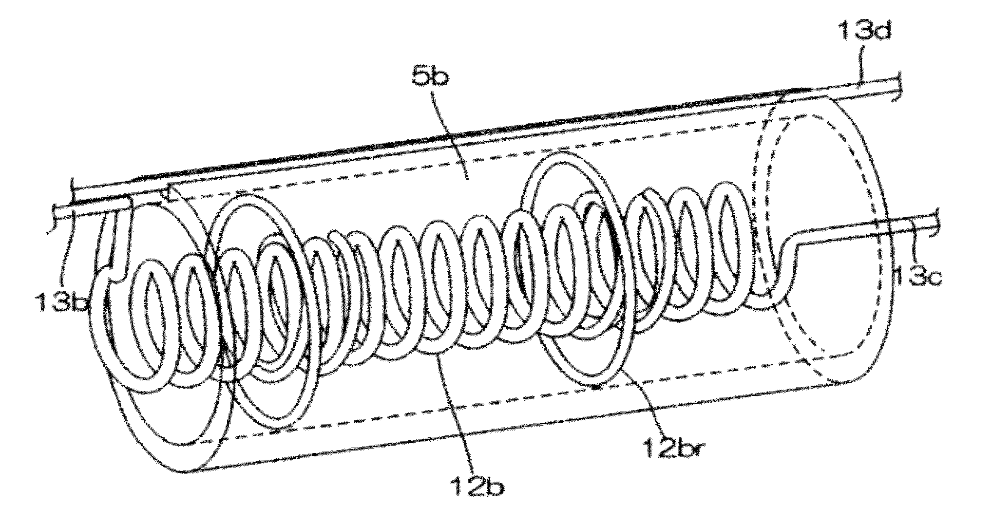
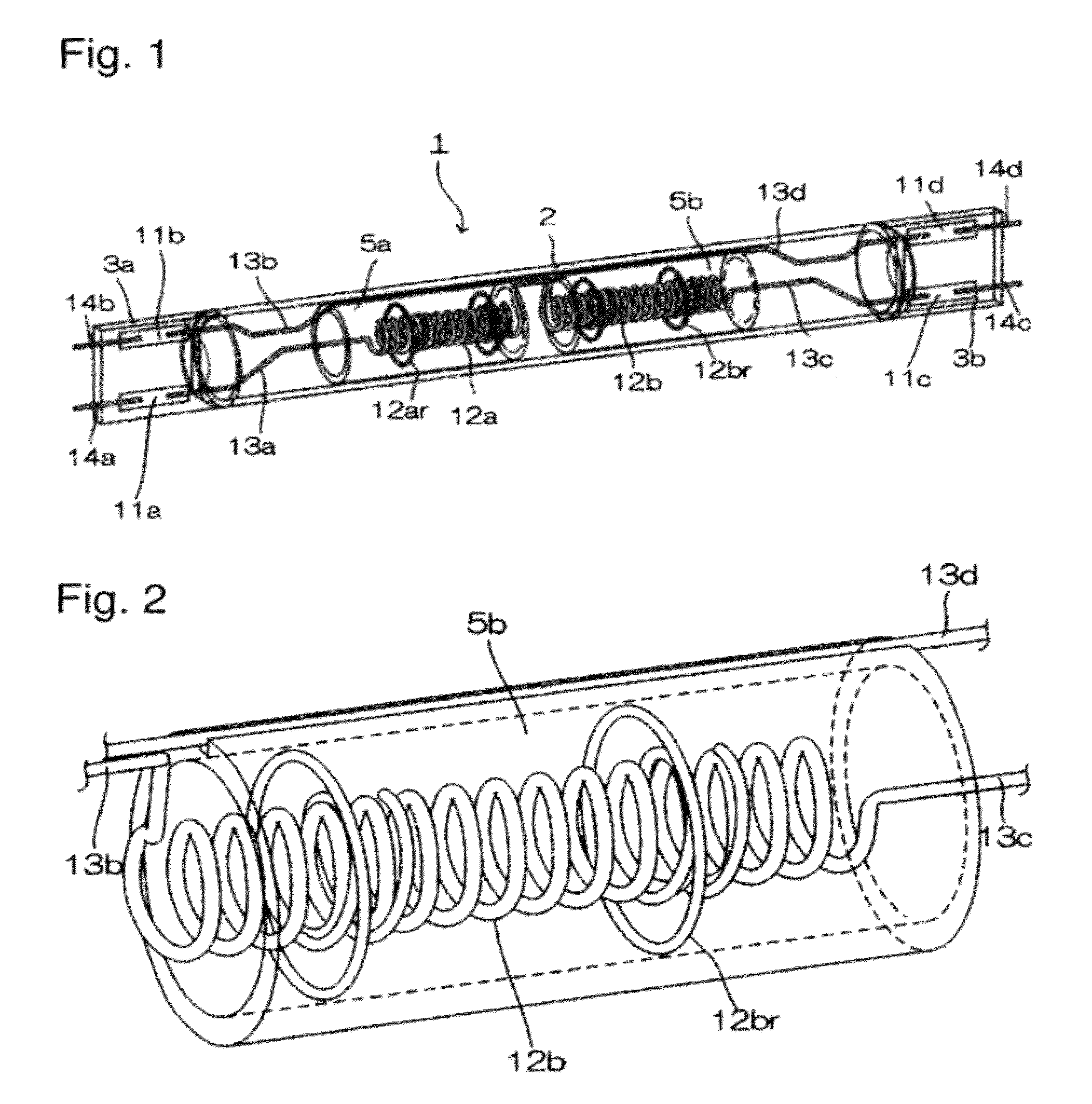
[0033]FIG. 1 is a perspective view showing a filament lamp 1 according to the

[0034]The filament lamp 1 is provided with a luminous tube 2 made of light-transparent material such as quartz glass. On both ends of the luminous tube 2 are formed sealing parts 3a and 3b with pinch seals in which metal foils 11a, 11b, 11c and 11d are buried. The inside of the luminous tube is sealed air-tight. Inside the luminous tube 2, filaments 12a and 12b, which are made of tungsten, for example, and divided into two parts in the axial direction of the luminous tube 2, are provided on the same axis along the axis of the luminous tube 2.

[0035]The filament 12a is electrically connected to an internal lead 13a on its one end side that is connected to the metal foil 11a and electrically connected to an internal lead 13d on the other end side that is connected to the metal foil 11d.

[0036]As with the filament 12a, the filament 12b is electrically connected to an internal lead 13c on its one end side that i...

second embodiment

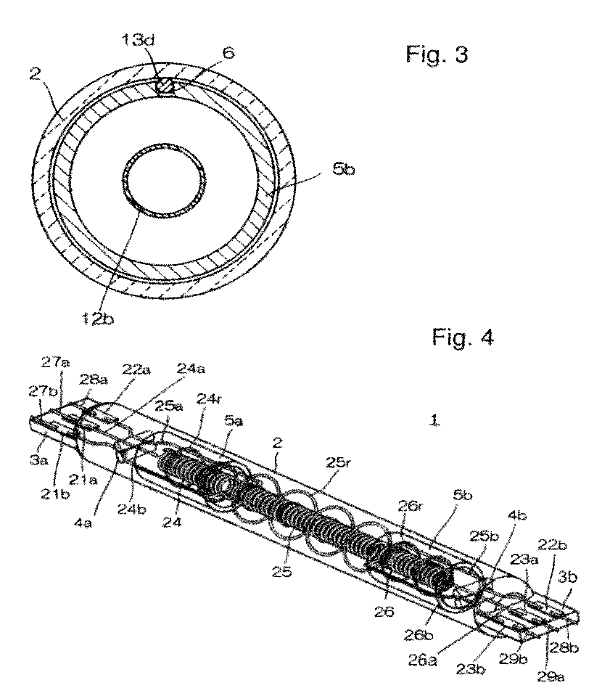
[0067]FIG. 4 shows a perspective view of the filament lamp 1 according to the

[0068]Inside the luminous tube 2 are disposed three filaments 24, 25 and 26 in the axial direction of the tube. Internal leads 24a, 24b, 26a and 26b connected to both ends of two filaments 24 and 26, which are disposed proximate to sealing parts 3a and 3b respectively, extend in the directions of the same sealing parts to be held by the sealing parts 3a and 3b, respectively. Moreover, internal leads 25a and 25b connected to both ends of the filament 25, which is disposed between two filaments 24 and 26, extend toward the opposite directions in the axial direction of the luminous tube 2 to be held at the sealing parts 3a and 3b on both ends.

[0069]Specifically, each of the internal leads 24a and 24b of the filament 24 proximate to the sealing part 3a on one end portion extend from the sealing part 3a and is connected to the end portion of the filament 24. Both of these internal leads 24a and 24b are held at t...

third embodiment

[0089]FIG. 7 is a perspective view showing the filament lamp 1 according to the

[0090]In the filament lamp 1 according to the third embodiment, as with the filament lamp 1 according to the second embodiment, internal leads 31a, 31b, 34a and 34b connected to both ends of two filaments 31 and 34, which are disposed proximate to sealing parts 3a and 3b respectively, extend in the direction of the same sealing part proximate to the filaments 31 and 34 to be held by the sealing parts 3a and 3b.

[0091]On the other hand, unlike the filament lamp 1 according to the second embodiment, at the central portion are disposed two filaments 32 and 33 to which electric power is independently supplied. Internal leads 33a and 33b connected to the filament 33 are connected to metal foils held in the sealing part 3b. Internal leads 32a and 32b connected to the other filament 32 extend in the directions of the sealing parts 3a and 3b on both ends and are held at the sealing parts 3a and 3b in such a manne...


PUM


Abstract

A filament lamp having a filament and an internal lead in which the filament is insulated from contact with the internal lead and prevent from moving during operation to maintain a uniform distribution of light. To this end, the filament lamp includes a luminous tube having an inner wall, and opposing ends on which sealing parts are formed. Multiple filaments are sequentially disposed inside the tube in an axial direction, and internal leads are connected to each filament. An insulating wall is provided along the inner wall of the luminous tube in the axial direction and is disposed around at least one of the multiple filaments. Internal leads running partly parallel to the filaments are positioned between the luminous tube and insulating wall and do not engage the ring supporters of the multiple filaments, which could cause the filaments to move and distribute light in a nonuniform pattern.

Description

BACKGROUND OF THE INVENTION[0001]1. Field of Invention[0002]The present invention relates to a filament lamp used for the heat treatment of a semiconductor wafer, solar cell or liquid crystal that provides a uniform distribution of light.[0003]2. Description of Related Art[0004]A light irradiation-type heat treatment device in the semiconductor manufacturing process has widely been used in the fields of film formation, diffusion and annealing. All of these heat treatment devices are capable of rapidly heating a semiconductor wafer or other plate-like object such that the temperature can be increased to 1000° C. or above within several seconds to several tens of seconds. There is a need for increasing the temperature at a faster speed recently, and consequently a need for increasing the amount of electric power inputted into such heat treatment devices during the time of the heat treatment. This is referred to as a spike anneal in which the temperature is increased at a high speed ex...

Claims


Application Information

Patent Timeline
Patent Type & Authority Patents(United States)
IPC IPC(8): H01K9/00
CPCH01K1/16H01K1/24H01K7/00H01K9/08H05B3/0047H01K5/02
Inventor NAKASHIMA, AKINOBUTANINO, KENJI
Owner USHIO DENKI KK
Why Eureka
Try Eureka