Deployable reflectarray antenna system

a technology of reflector antenna and antenna system, which is applied in the direction of collapsible antenna means, space fed arrays, antennas, etc., can solve the problems of increasing undesired side lobes, increasing antenna gain, and increasing antenna surface tolerances. , to achieve the effect of simple but effective deployment mechanism, reducing surface area, and increasing angular displacemen

Active Publication Date: 2012-10-16
THE UNITED STATES OF AMERICA AS REPRESETNED BY THE SEC OF THE AIR FORCE
View PDF7 Cites 19 Cited by
  • Summary
  • Abstract
  • Description
  • Claims
  • Application Information

AI Technical Summary

Benefits of technology

[0008]The present invention is a deployable reflectarray antenna system with a simple but effective deployment mechanism. A flat reflectarray antenna is subdivided through the center into n equally sized panels. The panels are then stacked one on top of the other reducing the surface area in the stowed configuration by a factor of nearly 1/n. A hollow cylindrical deployment mechanism is located at the center of the deployed antenna along with a waveguide and antenna feed. One panel is fixedly attached to the bottom of the cylinder. Guide slots are cut through the wall of the cylinder, one for each of the n-1 moveable panels. A panel mounting bracket is attached to each moveable panel near the center point where the panels converge. The panels are moveably attached to the deployment cylinder via the guide slots. In the stacked (stowed) configuration, the panels are

Problems solved by technology

At higher frequencies and larger deployed antenna diameters, it becomes more and more difficult to attain and to thereafter maintain required antenna surface tolerances.
Deviations from the desired shape reduce antenna gain and increase undesired side lobes.
For exam

Method used


Image

  • Deployable reflectarray antenna system
  • Deployable reflectarray antenna system
  • Deployable reflectarray antenna system

Examples


Embodiment Construction

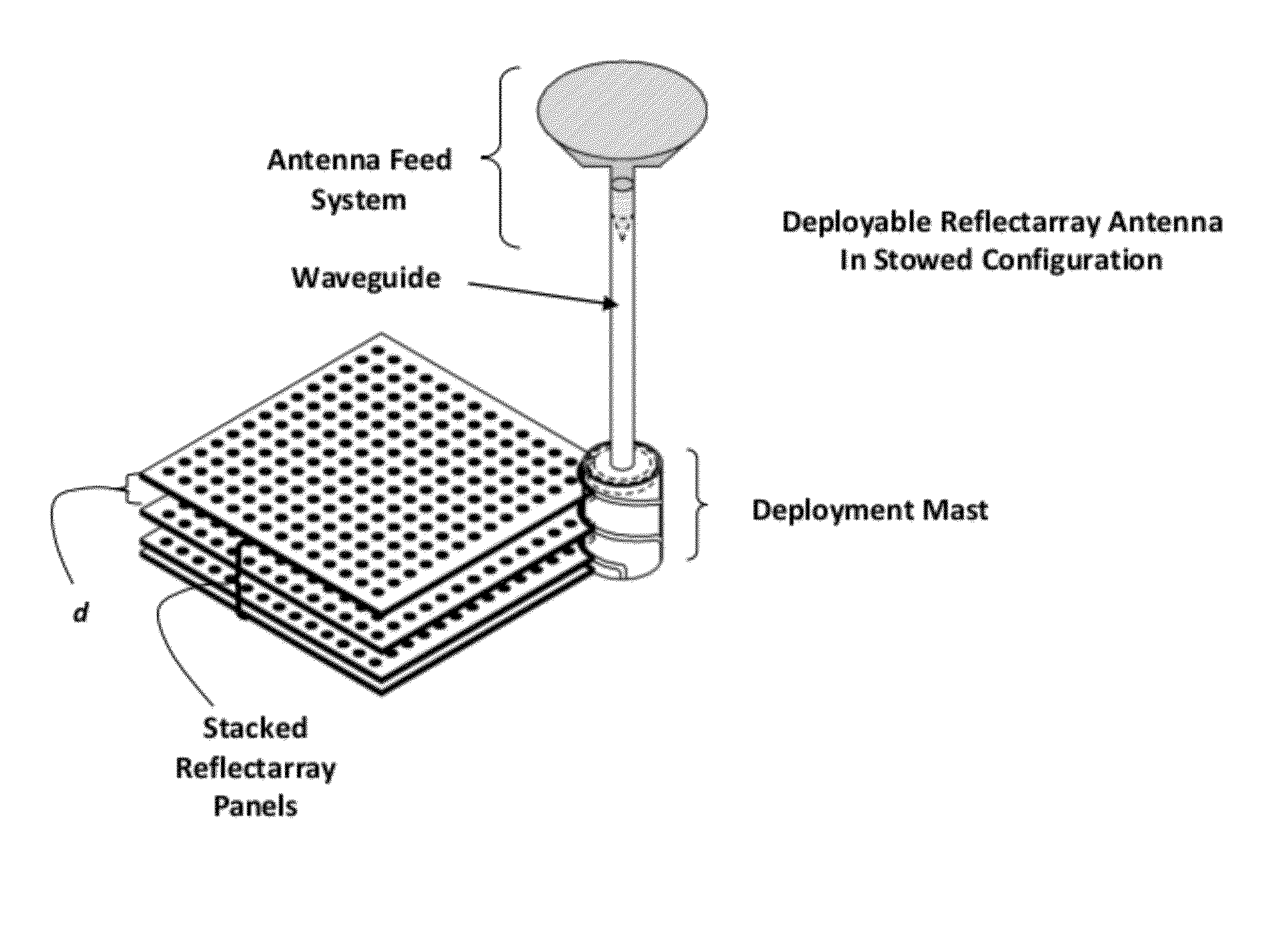
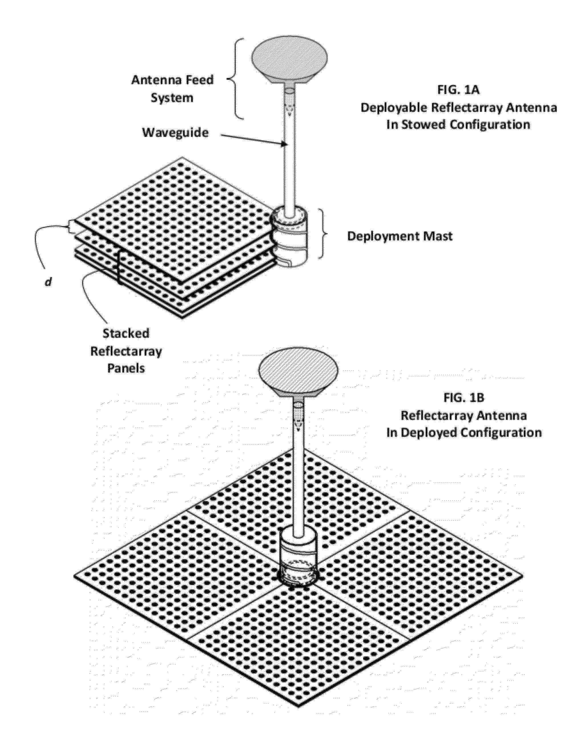
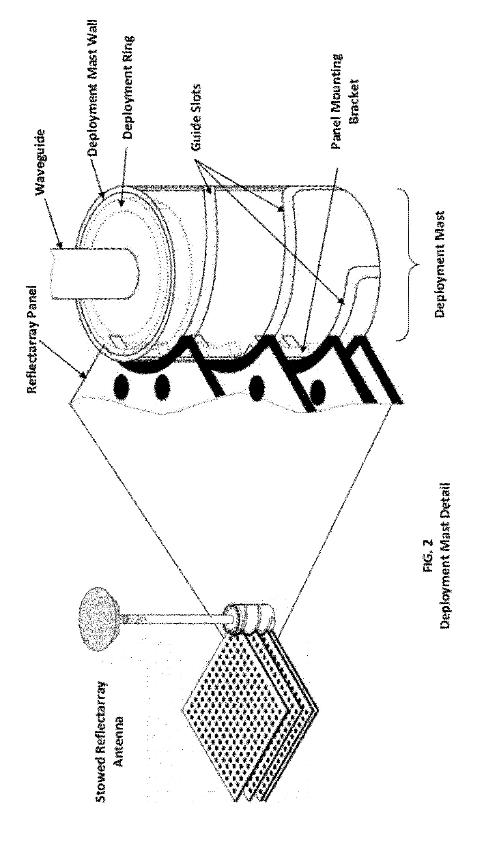
[0019]A deployable reflectarray antenna system is described that compactly packages a planar reflectarray antenna into a stack of component panels for launch and transportation and subsequently deploys them to a much larger operational antenna configuration that is combined with an integral waveguide and antenna feed. In the FIG. 1 example, four flat reflectarray panels make up the reflectarray antenna. The panels are attached by individual panel mounting brackets in the center area to the deployment mast. FIG. 1A shows the reflectarray antenna system in its stowed configuration occupying the footprint of a single flat panel. The bottom panel is fixedly attached to the bottom the deployment mast and the three movable panels are stacked above the fixed panel and vertically separated by a distance d. FIG. 1B shows the deployed configuration with a large reflective surface formed by the individual panels after being rotated and displaced downward along guide slots to lie in the plane o...


PUM


Abstract

A center-fed deployable reflectarray antenna system comprised of a stack of flat reflectarray panels, a deployment mast, a waveguide, and an antenna feed. The flat reflector in its deployed configuration is subdivided about its center into n equal panels. The stowed configuration has the n panels arranged in a vertical stack with each separated from the next by a small distance. Panel mounting brackets are attached to each panel at the center area where they would have converged in their deployed configuration. The deployment mast is a hollow cylinder with guide slots cut through its wall. The bottom panel is fixedly attached to the bottom of the deployment mast while the remaining panels are moveable attached to the guide slots. The guide slots are designed so that when going from the stacked to the deployed configuration each panel is moved with respect to the fixed panel along its guide slots a predetermined angle at which point it is dropped to the plane of the fixed panel. The waveguide is located along the central axis of the deployment mast and the antenna feed attached to the waveguide at the appropriate distance from the antenna reflector.

Description

STATEMENT OF GOVERNMENT INTEREST[0001]The conditions under which this invention was made are such as to entitle the Government of the United States under paragraph 1(a) of Executive Order 10096, as represented by the Secretary of the Air Force, to the entire right, title and interest therein, including foreign rights.BACKGROUND OF THE INVENTION[0002]The invention relates generally to deployable reflector antennas, and in particular to a deployable reflectarray antenna system.[0003]Reflector antennas have a long history of development for various uses in space. The need for antennas with ever larger collection surface areas led to the development of deployable antennas with relatively small stowed footprints that would fit within the limited dimensions of launch vehicle payloads. The bulk of these deployable reflector antennas are parabolic dish structures that are stowed and deployed by a variety of often complex mechanisms. At higher frequencies and larger deployed antenna diameter...

Claims


Application Information

Patent Timeline
IPC IPC(8): H01Q13/00
CPCH01Q1/08H01Q3/46H01Q21/0018H01Q21/065
Inventor FINUCANE, COLIN
Owner THE UNITED STATES OF AMERICA AS REPRESETNED BY THE SEC OF THE AIR FORCE
Why Eureka
Try Eureka