
Method and device for monitoring an exhaust-gas turbocharger

a technology of exhaust gas and turbocharger, which is applied in the direction of electrical control, mechanical vibration separation, instruments, etc., can solve the problem of comparatively high noise level of the turbocharger in the normal operating mode compared to other ambient noises within the motor vehicle, and achieve the effect of convenient and reliable operation method

Inactive Publication Date: 2012-10-23
CONTINENTAL AUTOMOTIVE GMBH
View PDF26 Cites 3 Cited by
  • Summary
  • Abstract
  • Description
  • Claims
  • Application Information

AI Technical Summary

Benefits of technology

[0009]An object of the present invention is therefore to provide an inexpensive and reliably operating method as a well as a corresponding device for monitoring an exhaust-gas turbocharger.
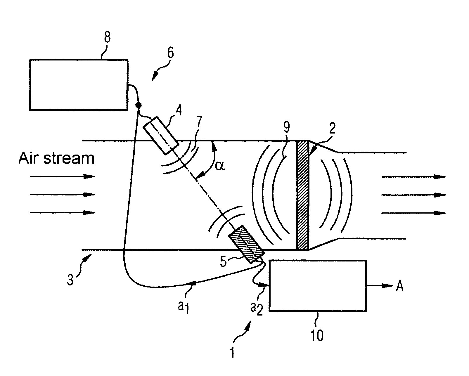
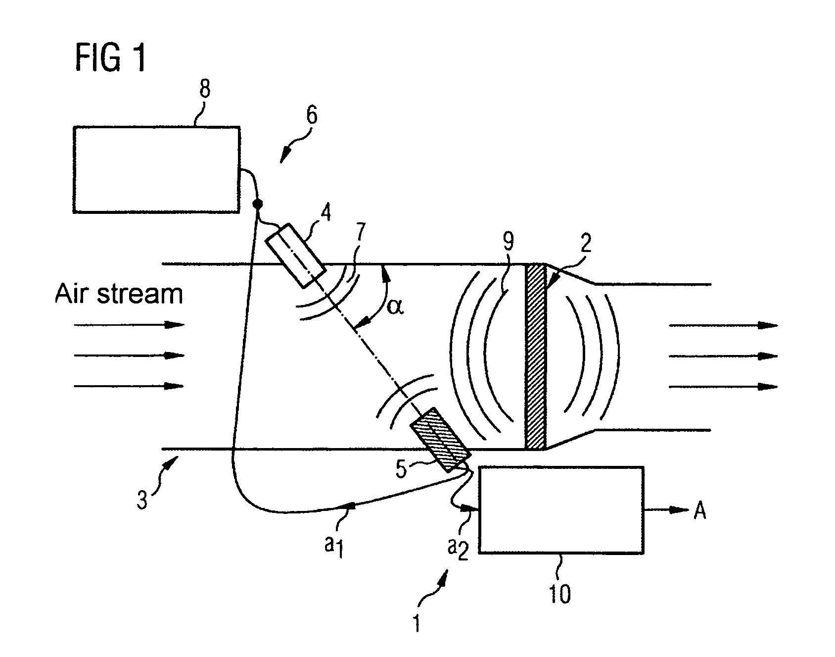
[0012]A noise level of a turbocharger which is in the normal operating mode compared to other ambient noises within a motor vehicle is comparatively high. Since the sound which is produced at the turbocharger propagates over large distances, in particular in the intake section, without significant damping, it is advantageous that the sound transducer which is to be provided according to the invention does not itself have to be mounted directly on the turbocharger. As a result, a corresponding sound transducer is also not subject to the known high temperatures and pressures in the region of the turbocharger. As a result, according to the invention even fewer robust and therefore relatively inexpensive sound transducers with a relatively small operating temperature range etc. can be used.

Problems solved by technology

A noise level of a turbocharger which is in the normal operating mode compared to other ambient noises within a motor vehicle is comparatively high.

Method used


Image

  • Method and device for monitoring an exhaust-gas turbocharger
  • Method and device for monitoring an exhaust-gas turbocharger
  • Method and device for monitoring an exhaust-gas turbocharger

Examples


first embodiment

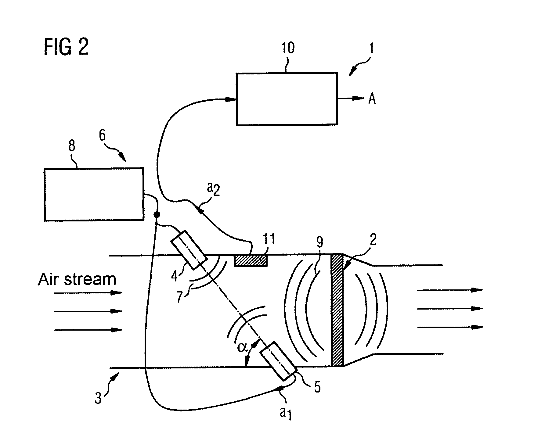
[0024]However, compared to FIG. 2, this results in overall simpler evaluation of the electrical measurement signals compared to the first embodiment given a certain degree of additional expenditure on apparatus by providing a further separate sound transducer 11 in the air inlet duct 3, since, in particular, it is not necessary to provide for the frequencies and for an output signal to be divided into two components a1, a2. Furthermore, the two ultrasonic transducers 3, 4 for the measuring of the air mass flow rate have an operating frequency which is significantly above the operating frequency, and therefore also a center frequency, of the ultrasonic transducer 11 which is provided for measuring the rotational speed of the turbocharger.

second embodiment

[0025]Since the noise level of the turbocharger 2 is very high compared to the respective ambient noise, and is, in particular, relatively dominant in the ultrasonic range, and in addition the sound which is produced propagates over large distances in the intake section 3 without significant damping, the ultrasonic air mass flow rate sensor 6 with its sound transducers 4, 5 and the separate sound transducer 11 provided in the second embodiment does not have to be mounted directly on the turbocharger 3. As a result, means for sensing the rotational speed of a turbocharger can also be installed at any position at which, according to the conventional design, known air mass flow rate sensors are installed. In this context, the ultrasonic sensors 4, 5, 11 generally have the advantage that, for example in designs of quartz transducers, they are comparatively insensitive to temperature, dirt and pressure. In addition, such sensors can be manufactured significantly more cost-effectively or ...


PUM


Abstract

The present invention relates to a method and a device for monitoring an exhaust-gas turbocharger of an internal combustion engine. In order to create an inexpensive and also reliably operating method and a corresponding device for monitoring an exhaust-gas turbocharger, it is proposed that a sound transducer which is designed to record rotational-speed dependent turbocharger operating noise is provided, which sound transducer is connected to an electronic system for frequency analysis for the output of a turbocharger rotational speed signal.

Description

PRIORITY CLAIM[0001]This is a U.S. national stage of application No. PCT / EP2007 / 055325, filed on 31 May 2007, which claims Priority to the German Application No: 10 2006 027 422.9, Filed: 13 Jun. 2006; the contents of both which are incorporated here by reference.BACKGROUND OF THE INVENTION[0002]1. Field of the Invention[0003]The present invention relates to a method and a device for monitoring an exhaust gas turbocharger of an internal combustion engine.[0004]2. Description of the Prior Art[0005]In internal combustion engines, it is known to cause an air / fuel mixture to burn by compressing it. The power output of the internal combustion depends on the ratio of the fuel mass flow rate to the air mass flow rate. The measurement of a respective air mass flow rate is carried out with an air mass flow rate sensor which is seated in the intake section of the internal combustion engine. Numerous modern internal combustion engines are equipped today with an exhaust-gas turbocharger which b...

Claims


Application Information

Patent Timeline
Patent Type & Authority Patents(United States)
IPC IPC(8): G01M15/02
CPCF02B39/16F02D41/18G01P3/44F02B37/14F02D41/0007F02D2041/285F02D2200/025G01F1/66F02D23/00B06B3/00
Inventor BIERL, RUDOLFLESSER, MARTINMEYER, ANDREASSTEUBER, FRANK
Owner CONTINENTAL AUTOMOTIVE GMBH
Learn More