Method, mandrel and device for the removal of coreless rolls of a stretch film

a coreless roll and stretch film technology, applied in the field of coreless roll removal of stretch film, can solve the problems of ineffective loss into the external environment, high cost of managing and disposing of said tubes, complex process, etc., and achieve the effects of reducing the consumption of pressurised air, saving energy, and constant valu

Active Publication Date: 2012-10-23
NO EL SRL
View PDF14 Cites 3 Cited by
  • Summary
  • Abstract
  • Description
  • Claims
  • Application Information

AI Technical Summary

Benefits of technology

[0017]The main object of the present invention is to provide a method for winding up coreless rolls of a stretch film normally used for packaging and wrapping palletized loads, by means of which the generation of an air cushion is made possible, suitable for providing and maintaining an expanding force for the internal turns of the roll, having a substantially constant value during the entire removal stroke of a roll or rolls, simultaneously enabling the consumption of pressurised air to be remarkably reduced, and energy to be saved.
[0018]A still further object of the present invention is to provide a mandrel, a device and an apparatus suitable for the above mentioned method, wherein the air loss through the holes of the mandrel during the taking off or removal of the rolls, is substantially eliminated, and the air pressure inside the mandrel is maintained at a substantially constant value.BRIEF DESCRIPTION OF THE INVENTION
[0019]All above can be achieved by a method according to claim 1, wherein a perforated mandrel is used according to claim 2, provided with an internal slidable piston for preventing the air to escape from the holes of the performed mandrel that are progressively uncovered by the rolls during the removal, as well as by means of a device according to claim 7.
[0020]In general, the invention consists in providing a tubular mandrel conformed with a single longitudinal air chamber for distribution of pressurized air, having a peripheral wall provided with a plurality of perforations or holes, wherein the pressurised air is supplied at the fore end of the air chamber, and wherein the volume of the air chamber, during the removal of at least one roll, or a plurality of rolls, is progressively reduced, starting from the rear to the fore end thereof, by advancing a piston inside the mandrel to gradually reduce the volume of the air chamber, and in which the piston is magnetically clamped to an external drive member, operatively connected, or suitable to be connected, to a roll pushing device.

Problems solved by technology

However, the use of normal, small winding tubes involves some complex process for forming the rolls, as well as high costs for managing and disposal of said tubes.
A common problem to the mandrels and the apparatuses of this type, which make use of perforated mandrels of conventional type, consists in the impossibility of preventing the air leakage and a control of the consumption of pressurised air required to provide the air cushion for the radial expansion and for supporting the rolls during the removal from the mandrel.
In the apparatuses of known type, the pressurised air usually is supplied at the rear end of an air chamber of the mandrel; therefore, sliding of the roll along the mandrel during the removal step, progressively uncovers the holes for the outflowing of the air that progressively become uncovered starting from the rear side of the roll; pressurised air escapes from the uncovered holes, which is ineffectively lost into the external environment.
Due to the ineluctable leakage of air, the pressure inside the mandrel progressively tends to reduce, producing a smaller thrust for expanding the internal turns, or an undesirable narrowing of the roll hole in the last section of the mandrel, with consequent frictional forces and difficulties for taking off, due to a reduction of the expanding force.
The use of separate air distribution chambers, in substitution of the single air chamber, has been proposed in order to maintain a cushion of air as homogeneous as possible during the removal of the rolls; however, such solution does not prevent the leakage of air typical of a conventional mandrel, since each single air chamber is again fed at the rear end thereof, and since the holes of the mandrel continue to be progressively uncovered during the removal of a roll, with consequent loss of air.

Method used


Image

  • Method, mandrel and device for the removal of coreless rolls of a stretch film
  • Method, mandrel and device for the removal of coreless rolls of a stretch film
  • Method, mandrel and device for the removal of coreless rolls of a stretch film

Examples


first embodiment

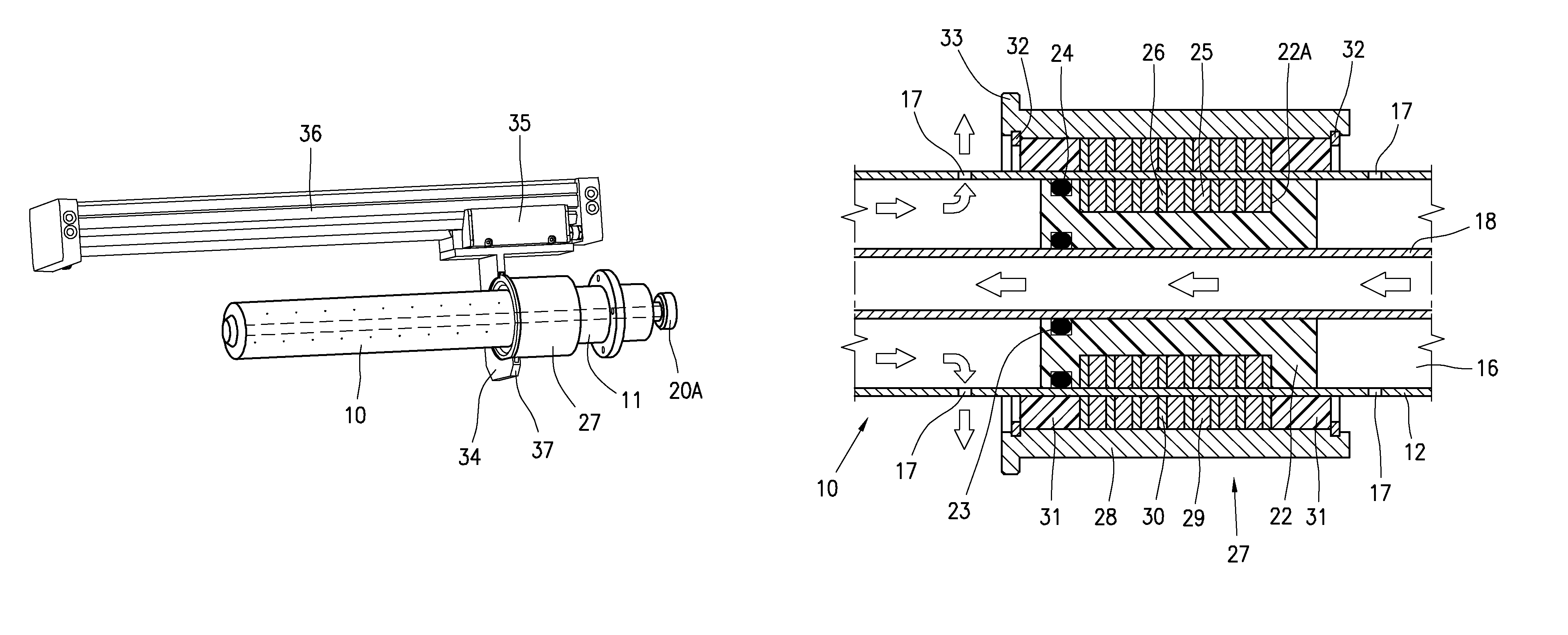
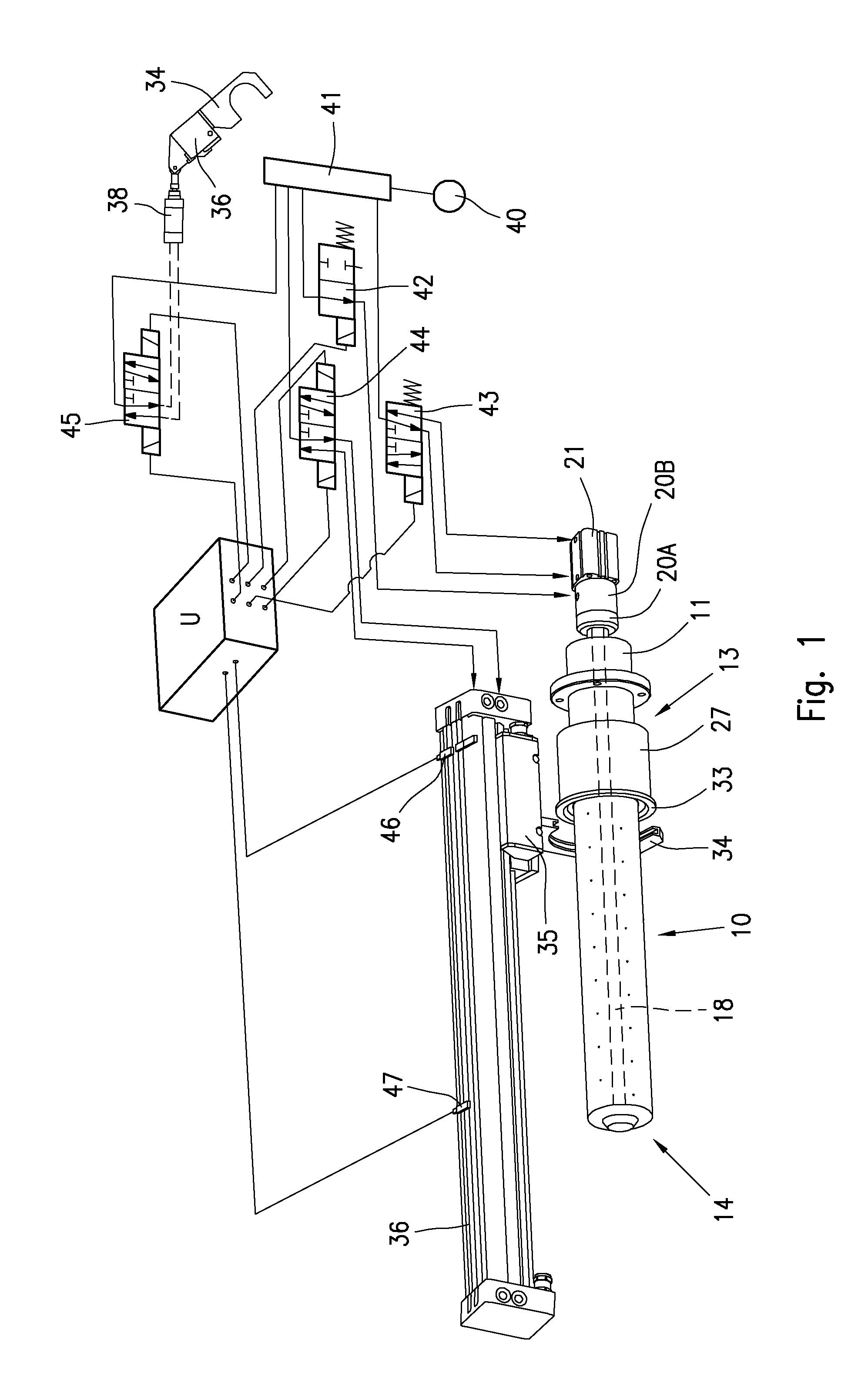
[0043]According to this first embodiment, shown in the FIGS. 1 to 4, the piston 22 comprises a cylindrical body of plastic material, provided with an annular seat 22A, wherein a first plurality of permanent magnets 25 of annular shape are arranged and axially spaced apart by a plurality of magnetic yokes or spacers 26.

[0044]The device further comprises an external drive member 27 magnetically clamped to the internal piston 22.

[0045]More precisely, in the example under consideration, the drive member 27 comprises a cylindrical sleeve 28 of aluminium or other magnetically non-conductive material, coaxially sliding with respect to the mandrel 10; inside the sleeve 28, a second plurality of permanent magnets 29 of annular shape and magnetic yokes or spacers 30 are arranged, facing corresponding magnets 25 and magnetic yokes or spacers 26 of the piston 22; two slides 31 of polythene or other plastic material, suitable for enabling a sliding substantially free of frictional forces, are re...

second embodiment

[0068]FIGS. 8 to 10 show the apparatus according to the present invention. The solution of FIGS. 8 to 10 differs from the preceding solution in respect to some characteristics of the magnetic drive member 27 for the piston 22. For all remaining, the solution of FIGS. 8-10 and the working mode do not substantially differ from the solution and the working mode of FIGS. 1 to 7; therefore, also in FIGS. 8-10 the same reference numbers have been used as FIGS. 1-7 to indicate similar or equivalent parts.

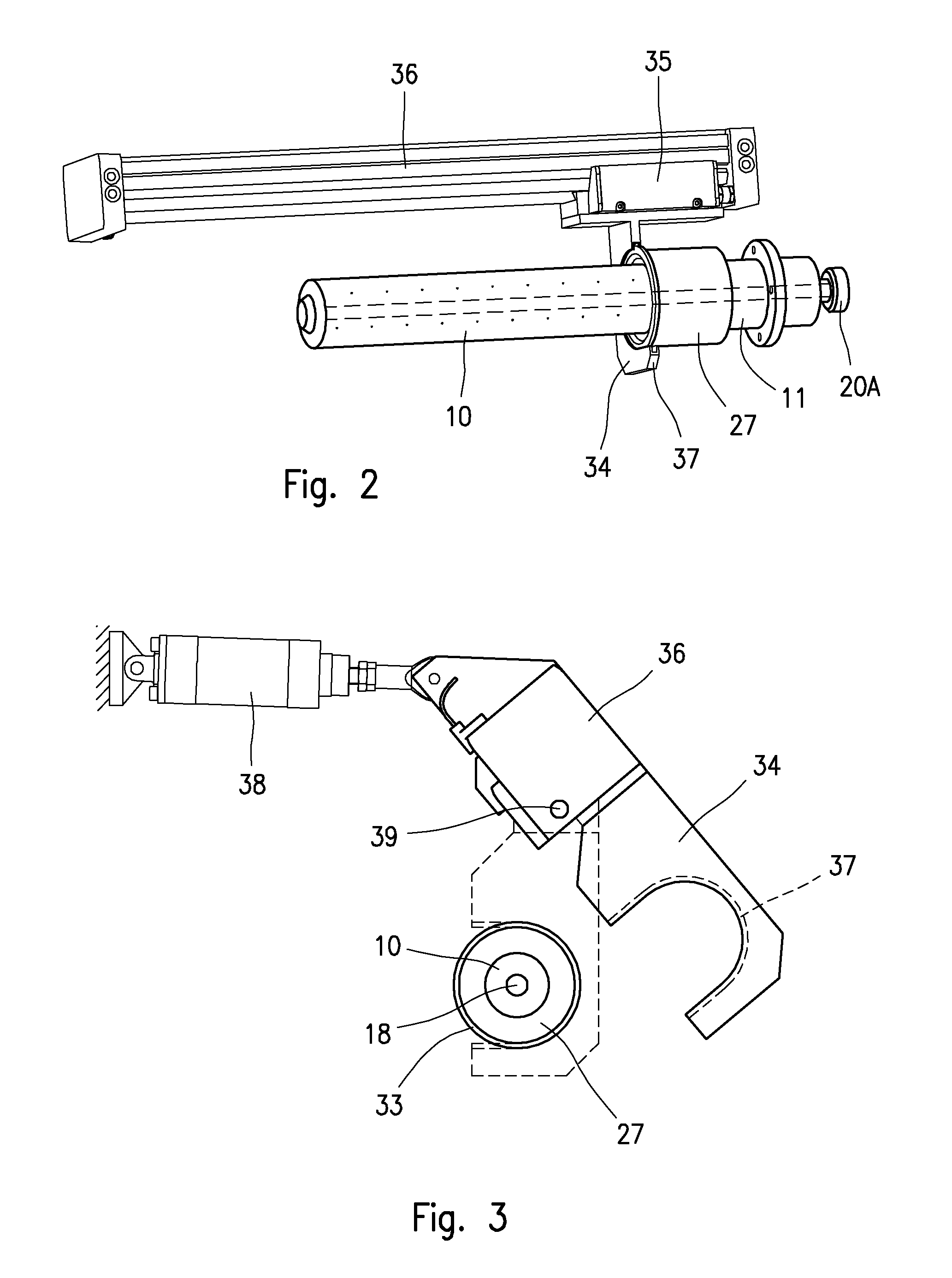
[0069]According to the preceding example of FIGS. 1-7, the operative connection between the piston 22 and the pushing device 34 occurs by means of a magnetic drive member 27, constantly clamped to the piston 22, wherein the drive member 27 can be engaged and disengaged from the pushing device 34 by an angular rotation of the control cylinder 36.

[0070]FIGS. 8 to 10 show a second, more structurally simple solution, which differs from the preceding solution in the different conformation of th...


PUM


Abstract

A method, a mandrel and a device for removing coreless rolls of a plastic film. The mandrel comprises a tubular body having a plurality of radial holes, conformed with a chamber for distributing pressurized air, in which a piston suitable for being magnetically coupled with an external drive member slides. When a roll must be removed, pressurized air is supplied to the fore end of the mandrel, and escapes from all the holes to expand the internal turns of the roll which can be taken off without friction. As the roll advances along the mandrel, the magnetically driven piston progressively reduces the volume of the air chamber preventing at the same time the air to escape from the holes that progressively come to lie on the rear side of the mandrel, with consequent saving of compressed air.

Description

[0001]This application is a U.S. national stage of PCT / EP2010 / 057854 filed on Jun. 4, 2010 which claims priority to and the benefit of Italian Application No. MI2009A001130 filed on Jun. 25, 2009, the contents of which are incorporated herein by reference.BACKGROUND OF THE INVENTION[0002]The present invention relates to the removal of coreless rolls of a stretch film wound up on a perforated mandrel, by means of which a cushion of pressurised air is generated to cause a radial expansion and compaction of the internal turns of the coils, allowing said coils to be slidably removed without frictional forces.[0003]In particular, the invention is directed to a method as well as to a mandrel and a device for removing coreless rolls of a stretch film in winding machines, said method, mandrel and device being suitable for achieving a substantial reduction of the compressed air consumption.[0004]The invention is suitable for winding and removing coreless rolls of stretchable plastic films, n...

Claims


Application Information

Patent Timeline
Patent Type & Authority Patents(United States)
IPC IPC(8): B65H19/22
CPCB65H19/2276B65H19/2292B65H2406/11B65H2406/14B65H2555/13
Inventor PELLENGO GATTI, ROBERTO
Owner NO EL SRL
Why Eureka
Try Eureka