Flying wing aircraft with modular missionized elements

a technology of flight wing aircraft and modular design, applied in the field of modular design of aircraft, can solve the problems of not being particularly new in concept, not being able to achieve multiple missions, and not being able to achieve the effect of multiple missions,

Active Publication Date: 2012-10-23
NORTHROP GRUMMAN SYST CORP
View PDF27 Cites 18 Cited by
  • Summary
  • Abstract
  • Description
  • Claims
  • Application Information

AI Technical Summary

Problems solved by technology

However, none of these aircraft are designed to accomplish multiple missions through being configured in the production line for traditionally different missions.
However, this concept is not particularly new.
Typically, this requires larger engines and or an increase in wing length.
Furthermore, none of these concepts disclose an aircraft design that is modular and primarily only modifies a portion of the fuselage which carries the payload.

Method used


Image

  • Flying wing aircraft with modular missionized elements
  • Flying wing aircraft with modular missionized elements
  • Flying wing aircraft with modular missionized elements

Examples


Embodiment Construction

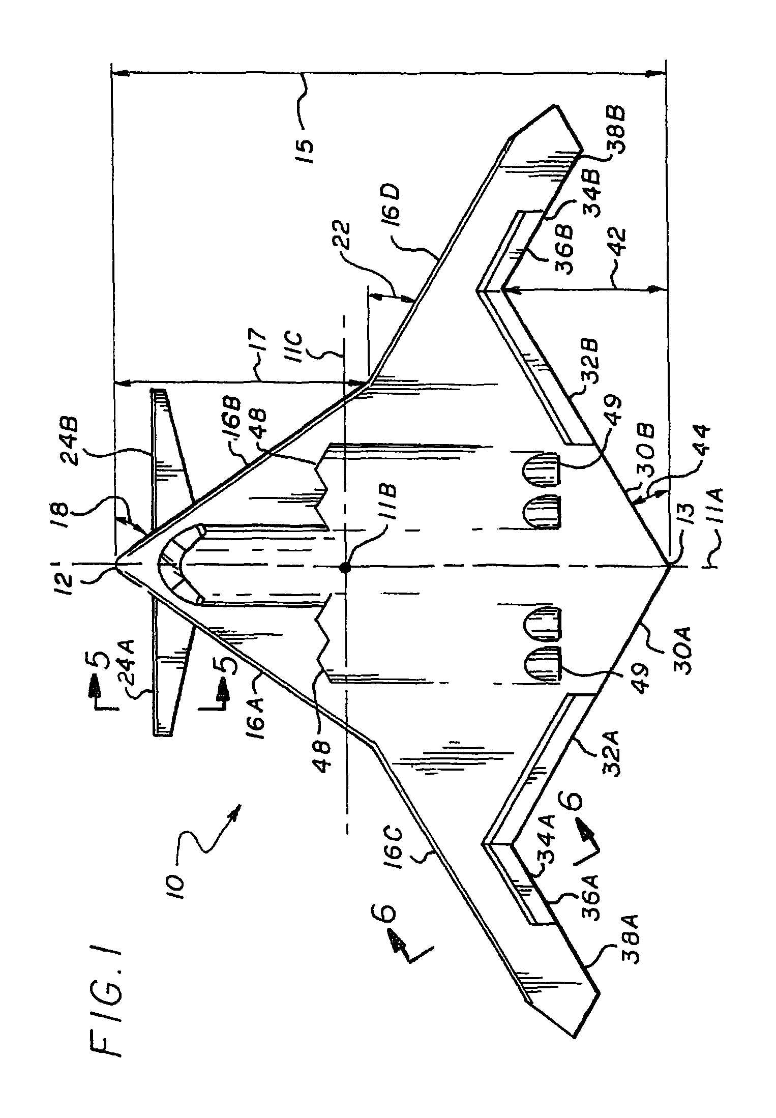
[0025]Referring to FIGS. 1-5, the flying wing aircraft, is generally designated by numeral 10 and has longitudinal axis 11A, vertical axis 11B and a horizontal axis 11C. The aircraft 10 includes a nose end 12, tail end 13 with an overall length 15. The right and left inner leading edges 16A and 16B extend back from the nose end 12 over a distance 17 at a sweep angle 18, of between 30 and 80 degrees. The distance 17 is about 40 to 60 percent of the total length 15 of the aircraft. The left and right outer leading edges 16C and 16D A have a sweep angle 22, of between 0 and 80 degrees as measured from a local horizontal.

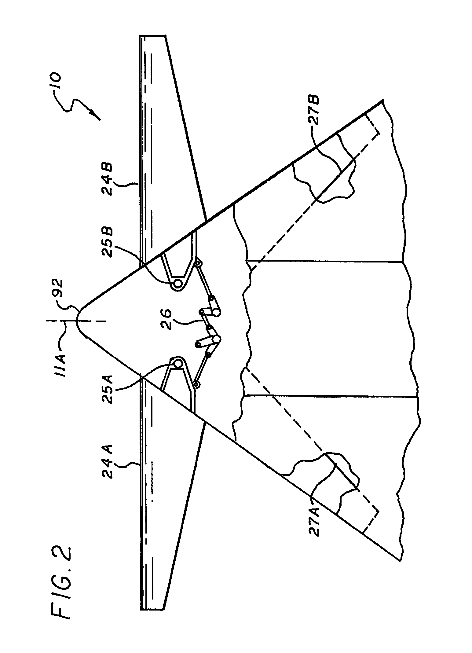
[0026]Mounted in proximity to the left and right inner leading edges 16A and 16B are right and left canards 24A and 24B having Coanda effect airfoil cross-sections (see FIG. 5). The canards 24A and 24B have an axis of rotation 25A and 25B, respectively and an actuation system 26 that retract the canards to form part of the leading edge 16A and 16B or the canards may be ...


PUM


Abstract

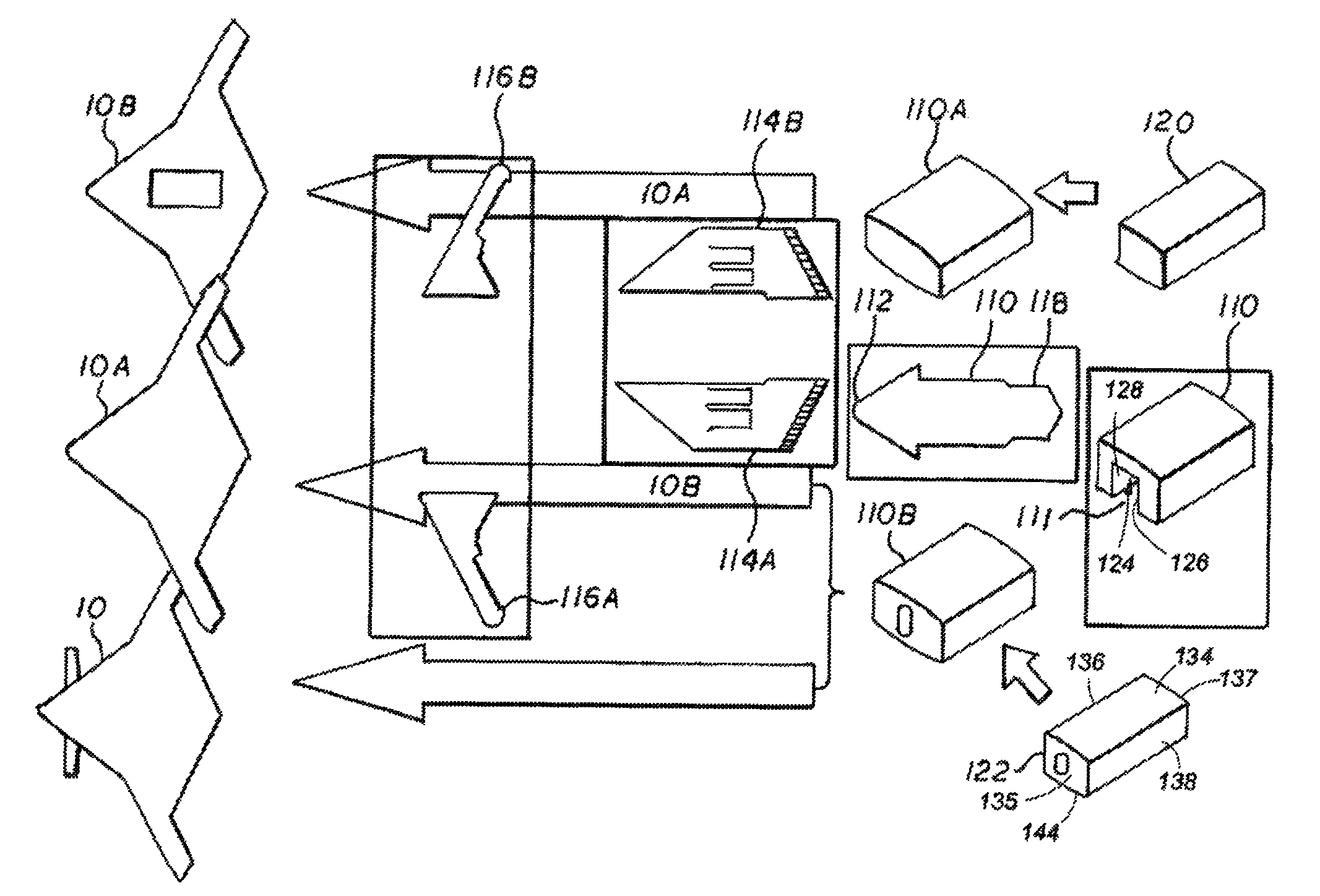
The invention is a flying wing aircraft having a forward fuselage; an aft fuselage segment; a propulsion segments adapted to mate to the fuselage segments; a pair of wing segments adapted to mate with the propulsion segments. The invention further includes a center section adapted to fit between the forward and aft fuselage sections; the center section adapted to receive multiple compartment systems.

Description

BACKGROUND OF THE INVENTION[0001]1. Field of the Invention[0002]The invention relates to the field of aircraft manufacturing and, in particular, to a modular design for an aircraft providing an increase in structural commonality while retaining high performance in a single aircraft to architecture designed for multiple missions.[0003]2. Description of Related Art[0004]The typical aircraft is designed for a few, relatively common mission, for example, a passenger airliner can be converted into a cargo aircraft by removing the passenger seats and increasing the size of the doors. In fact, they can be converted into military refueling aircraft, but with notable structural changes. Of course different weapons systems can be loaded on the wings of military aircraft. Military bombers can have their bomb bays constructed to convert to multiple different weapons carriage systems (e.g. rotary launcher assemblies or bomb rack assemblies). However, none of these aircraft are designed to accomp...

Claims


Application Information

Patent Timeline
Patent Type & Authority Patents(United States)
IPC IPC(8): B64C1/22
CPCB64C3/141B64C5/12B64C9/38B64C39/10B64C39/12B64C2039/105
Inventor WESTRA, BRYAN WAYNESATO, ROXANNE MARIESHULTZ, DOUGLAS ELLWOODKERSWELL, JAMES FRANKLINPETERSEN, PERRY BRUCECOLLINS, SCOTT WALTER
Owner NORTHROP GRUMMAN SYST CORP
Why Eureka
Try Eureka