Supercharge Your Innovation With Domain-Expert AI Agents!

Control apparatus for belt-type continuously-variable transmission

a control apparatus and continuously variable technology, applied in the direction of machines/engines, transportation and packaging, road transportation, etc., can solve the problems of high hydraulic pressure of the continuously variable transmission type and the difficulty of improving fuel consumption, and achieve the effect of improving fuel consumption

Inactive Publication Date: 2012-10-23
JATCO LTD +1
View PDF6 Cites 6 Cited by
  • Summary
  • Abstract
  • Description
  • Claims
  • Application Information

AI Technical Summary

Benefits of technology

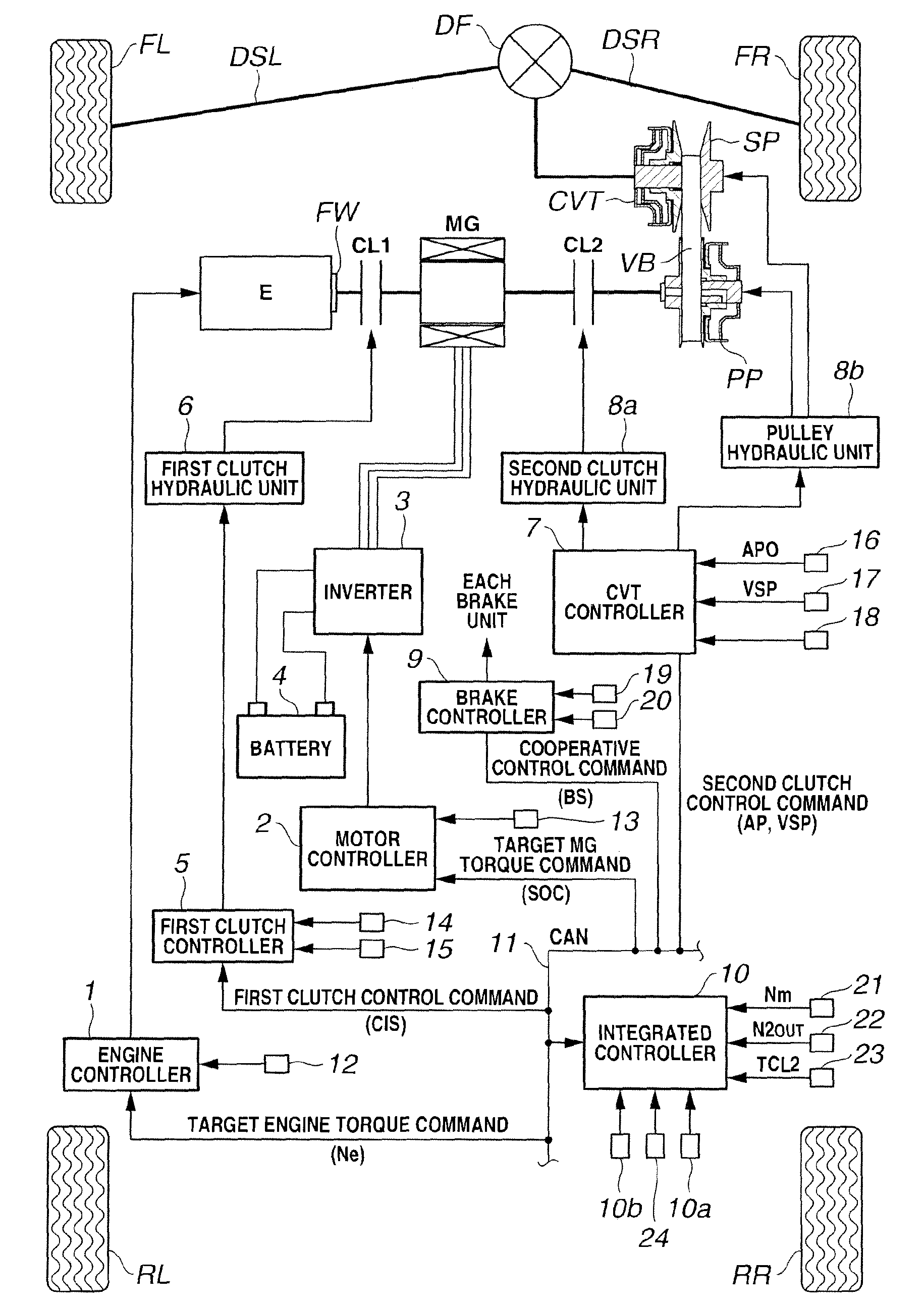
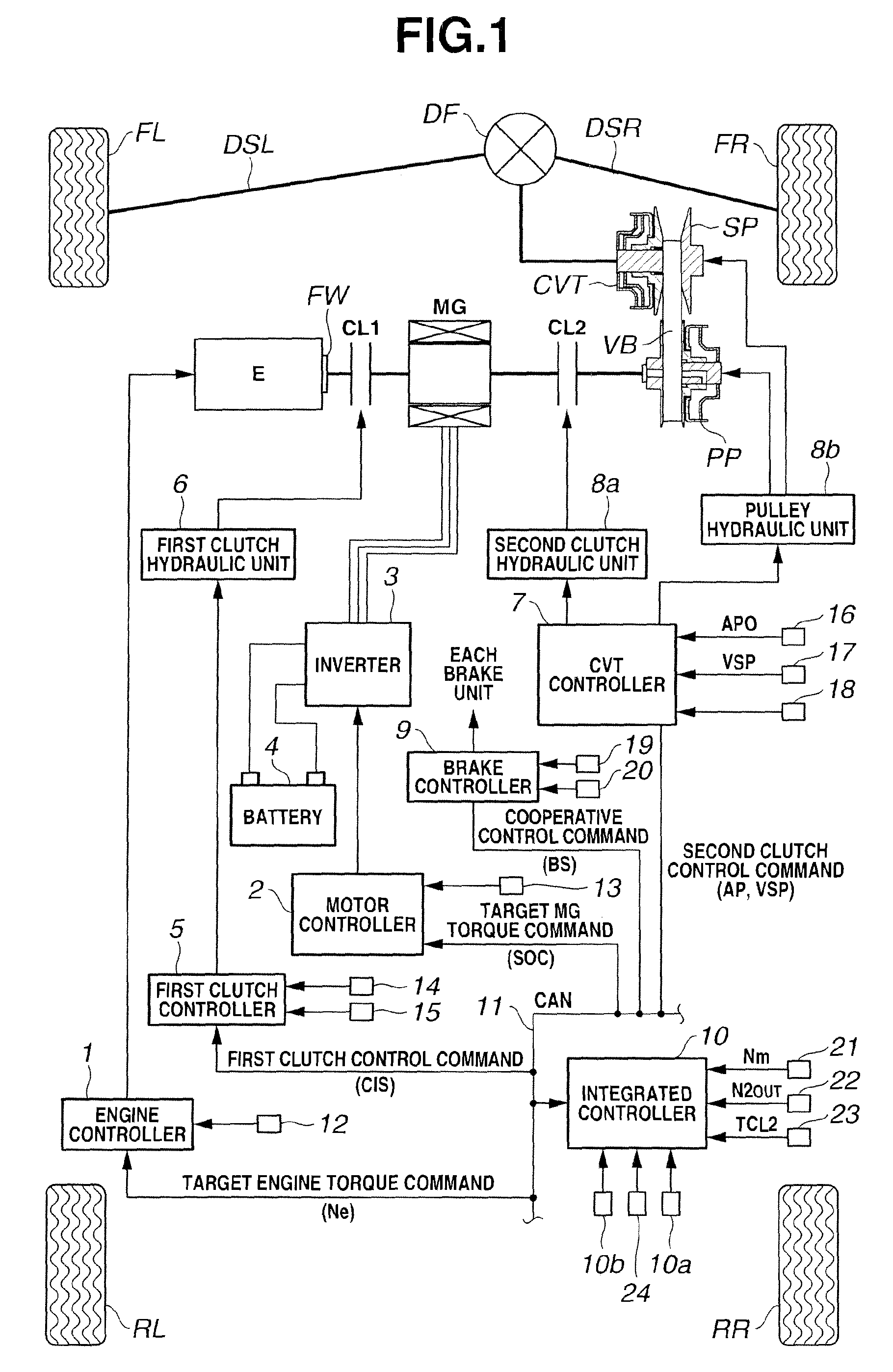
The present invention provides a control apparatus for a belt-type continuously-variable transmission that is designed to improve fuel consumption. The apparatus includes a hydraulic pressure control section and a torque control section that work together to bring the belt and the pulleys to a slip state, and a target rotational speed calculating section and a rotational speed control section that work together to achieve a desired transmission gear ratio. The apparatus also includes a capacity side pulley pressure setting section that sets a hydraulic pressure based on the deviation between the desired torque and the actual torque of the driving source. The result is a more efficient and effective control of the belt-type continuously-variable transmission that leads to improved fuel consumption.

Problems solved by technology

However, the above-described belt-type continuously-variable transmission needs a high hydraulic pressure for suppressing the belt slippage.
A pump friction becomes high, and accordingly it is difficult to improve fuel consumption.

Method used


Image

  • Control apparatus for belt-type continuously-variable transmission
  • Control apparatus for belt-type continuously-variable transmission
  • Control apparatus for belt-type continuously-variable transmission

Examples


second embodiment

[0079]Next, a control apparatus for a belt-type continuously-variable transmission according to a second embodiment of the present invention is illustrated. The control apparatus according to the second embodiment is identical in a basic control configuration to the control apparatus according to the first embodiment. The following explanation is directed only to points different from the first embodiment, and repetitive explanation is omitted. FIG. 8 is a time chart showing a slip rate control operation in the second embodiment. In the first embodiment, engine E and motor generator MG are simultaneously used. In the second embodiment, the torque is adjusted only by engine E, unlike the first embodiment. Accordingly, it is possible to attain the effects shown in (1) and (2) of the first embodiment. Moreover, it is possible to simplify the control logic by adjusting the input torque only engine E.

third embodiment

[0080]Next, a control apparatus for a belt-type continuously-variable transmission according to a third embodiment of the present invention is illustrated. The control apparatus according to the third embodiment is identical in a basic control configuration to the control apparatus according to the first embodiment. The following explanation is directed only to points different from the first embodiment, and repetitive explanation is omitted. FIG. 9 is a time chart showing a slip rate control operation in the third embodiment. In the first embodiment, engine E and motor generator MG are simultaneously used. In the third embodiment, the torque is adjusted only by motor generator MG, unlike the first embodiment. Accordingly, it is possible to attain the effects shown in (1) and (3) of the first embodiment. Moreover, it is possible to simplify the control logic by adjusting the input torque only by motor generator MG. Furthermore, motor generator MG has a response higher than that of e...

fourth embodiment

[0081]Next, a control apparatus for a belt-type continuously-variable transmission according to a fourth embodiment of the present invention is illustrated. The control apparatus according to the fourth embodiment is identical in a basic control configuration to the control apparatus according to the first embodiment. The following explanation is directed only to points different from the first embodiment, and repetitive explanation is omitted. In the first embodiment, slip rate calculating section 402 and torque adjusting section 403 adjust the engine torque and / or the motor generator torque, and thereby control the slip rate. The control apparatus according to the fourth embodiment includes an engine speed control section 404 configured to control the engine speed as the target value, and thereby to control the slip rate, in place of slip rate calculating section 402 and torque adjusting section 403 of the first embodiment.

[0082]FIG. 10 is a block diagram showing a control configu...


PUM


Abstract

A belt continuously-variable transmission control apparatus includes: a belt continuously-variable transmission including; a primary pulley arranged to receive a torque from a driving source; a secondary pulley arranged to output the torque to driving wheels; a belt wound around the primary pulley and the secondary pulley; a hydraulic pressure control section configured to control a hydraulic pressure of one of the primary pulley and the secondary pulley which is a capacity side, and thereby to bring the belt, the primary pulley and the secondary pulley to a slip state; and a torque control section configured to control the torque of the driving source, and thereby to bring the slip state to a predetermined slip state.

Description

BACKGROUND OF THE INVENTION[0001]This invention relates to a control apparatus for a belt-type continuously-variable transmission.[0002]U.S. Patent Application Publication No. 2005-107195 (corresponding to Japanese Patent Application Publication No. 2005-147264) discloses a control apparatus for a belt-type continuously-variable transmission which is configured to control a hydraulic pressure so as to suppress a slip between a belt and pulleys.SUMMARY OF THE INVENTION[0003]However, the above-described belt-type continuously-variable transmission needs a high hydraulic pressure for suppressing the belt slippage. A pump friction becomes high, and accordingly it is difficult to improve fuel consumption.[0004]It is an object of the present invention to provide a control apparatus for a belt-type continuously-variable transmission which is devised to solve the above mentioned problem, and to improve the fuel consumption.[0005]According to one aspect of the present invention, a belt conti...

Claims


Application Information

Patent Timeline
Patent Type & Authority Patents(United States)
IPC IPC(8): F16H61/00F16H61/662F16H59/74B60W10/10B60K6/48B60K6/543B60W10/04B60W10/06B60W10/08B60W10/101B60W10/105B60W10/107B60W20/00F02D29/00F16H59/18F16H59/42F16H59/44F16H59/70F16H61/02F16H63/46F16H63/50
CPCF16H61/66272B60L2260/14Y02T10/76Y10T477/624Y10T477/675Y10T477/6242Y10T477/67B60L2200/26F16H61/662F16H61/66F16H61/00F16H61/02F16H63/46F16H63/00F16H63/50B60W10/04
Inventor YAMANAKA, TSUYOSHIISHII, SHIGERUSHIMANAKA, SHIGEKI
Owner JATCO LTD
Features
  • R&D
  • Intellectual Property
  • Life Sciences
  • Materials
  • Tech Scout
  • Unparalleled Data Quality
  • Higher Quality Content
  • 60% Fewer Hallucinations
Learn More