
Power amplifier pre-distortion

a technology of power amplifiers and distortion reduction, applied in the field of power amplifier distortion reduction, can solve the problems of affecting the quality of in-band signal, and affecting the operation of power amplifiers. the effect of reducing the distortion of power amplifiers

Active Publication Date: 2012-10-23
AVAGO TECH INT SALES PTE LTD
View PDF88 Cites 17 Cited by
  • Summary
  • Abstract
  • Description
  • Claims
  • Application Information

AI Technical Summary

Benefits of technology

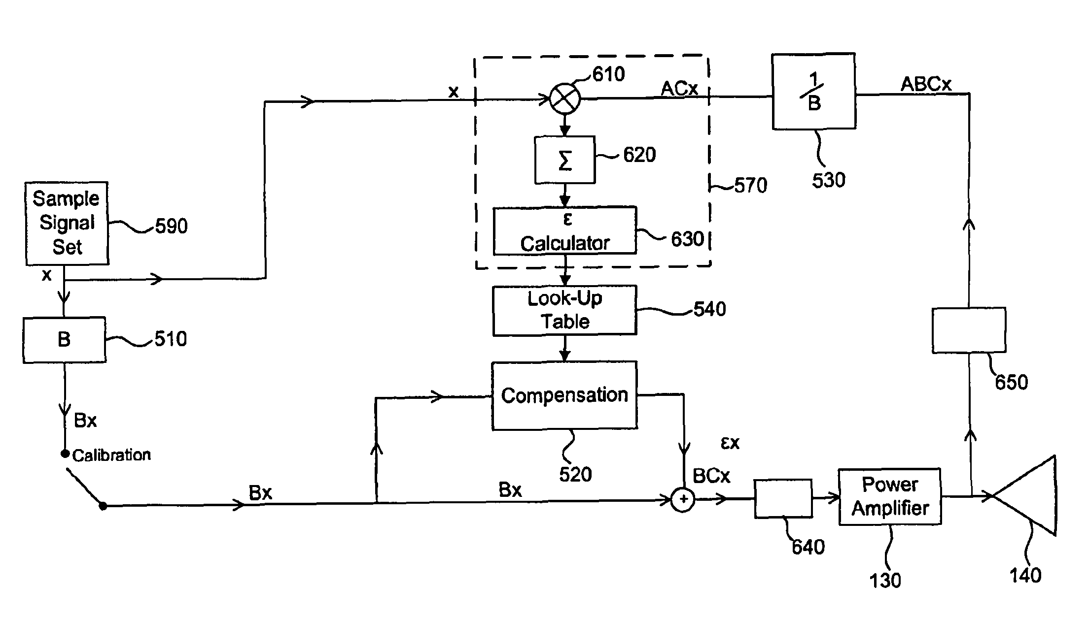
The present invention is about a technique to reduce distortion in power amplifiers. It does this by pre-distorting the input signal to the amplifier in a way that offsets the distortion generated by the amplifier's nonlinearities. This pre-distortion is determined by a calibration procedure using a set of tones over the nonlinear operating range of the amplifier. The amount of pre-distortion needed is stored in a look-up table that can be read in real-time, so the appropriate level of pre-distortion can be added to the input signal. In a MIMO system containing multiple power amplifiers, each amplifier is provided with a look-up table for real-time pre-distortion of the input signal to each amplifier, taking into account the varying coupling that may be present between them when they are in an active state. The technical effect of this invention is to improve the efficiency and accuracy of power amplifiers in wireless communication systems.

Problems solved by technology

However, concurrent with these improvements in link coverage and power amplifier efficiency, the distortion in the output data signal unfortunately increases with increasing power level.
It also reveals itself as a degradation of the quality of the in-band signal such that larger constellations and higher throughput rates are inhibited at higher transmission powers.
Such distortion, a result of the nonlinearities in the power amplifier, directly diminishes the useful output power range of the power amplifier.
Such off-chip power amplifiers are expensive.
Moreover, they do not provide the same integration opportunities afforded by an on-chip amplifier, such as optimization of associated power amplifier (PA) circuitry, integration of the power supplies, consistency of PAs (from one to the next), ease of testing and calibration, and reliable connectivity.

Method used


Image

  • Power amplifier pre-distortion
  • Power amplifier pre-distortion
  • Power amplifier pre-distortion

Examples


Embodiment Construction

[0025]This specification discloses one or more embodiments that incorporate the features of this invention. The embodiment(s) described, and references in the specification to “one embodiment”, “an embodiment”, “an example embodiment”, etc., indicate that the embodiment(s) described may include a particular feature, structure, or characteristic, but every embodiment may not necessarily include the particular feature, structure, or characteristic. Moreover, such phrases are not necessarily referring to the same embodiment. Furthermore, when a particular feature, structure, or characteristic is described in connection with an embodiment, it is submitted that it is within the knowledge of one skilled in the art to effect such feature, structure, or characteristic in connection with other embodiments whether or not explicitly described.

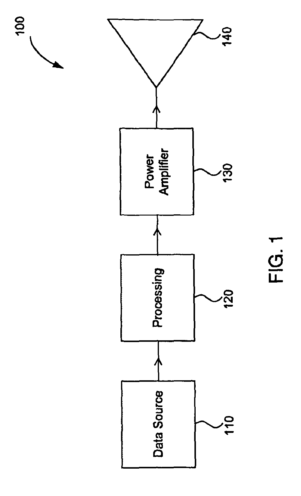
[0026]FIG. 1 illustrates typical functionality in a data communications transmitter 100. A data source 110 outputs data that is subsequently fed into a p...


PUM


Abstract

The present invention is directed to systems and methods for reducing the distortion of power amplifiers. In particular, methods and systems are described that enable a determination of a pre-distortion correction signal to be determined, which when added to the nominal signal, a reduction in the distortion of the power amplifier results. In addition, methods and systems are described that enable calibration of individual power amplifiers to be accomplished for use with the above described approach. More specifically, the methods and systems are described for use in a MIMO application. These approaches may be applied to on-chip power amplifiers, off-chip power amplifiers, or any combination thereof.

Description

CROSS REFERENCE TO RELATED APPLICATIONS[0001]The present application claims the benefit of U.S. Provisional Patent Application No. 60 / 929,150, entitled “Power Amplifier Pre-Distortion”, filed on Jun. 15, 2007, which is hereby expressly incorporated by reference in its entirety.BACKGROUND OF THE INVENTION[0002]1. Field of the Invention[0003]The present invention relates generally to power amplifiers, and more specifically to the pre-distortion of power amplifiers.[0004]2. Related Art[0005]A critical component of any communications system is the power amplifier in the transmitter. The function of the power amplifier is to amplify an input data signal and thereby create a high powered version of that input data signal for subsequent output into a transmission channel. The greater the amplification capability of the power amplifier, the greater the resulting output power level, and therefore the larger the geographic area covered by the communications system. In addition to the increase...

Claims


Application Information

Patent Timeline
Patent Type & Authority Patents(United States)
IPC IPC(8): H03F1/26
CPCH03F1/3247H03F3/24H03F3/68H03F2200/451H03F2200/468H03F2201/3233
Inventor YOUNG, CHRISTOPHERSIMPSON, ELIAS
Owner AVAGO TECH INT SALES PTE LTD
Learn More