Image waveguide having non-parallel surfaces

Active Publication Date: 2012-10-23
GOOGLE LLC
View PDF64 Cites 27 Cited by
  • Summary
  • Abstract
  • Description
  • Claims
  • Application Information

AI Technical Summary

Problems solved by technology

There is certain to be new found practical and leisure applications as the technology evolves; however, many of these applications are limited due to the cost, size, field of view, form factor, and efficiency of conventional optical systems used to implement existing HMDs.

Method used


Image

  • Image waveguide having non-parallel surfaces
  • Image waveguide having non-parallel surfaces
  • Image waveguide having non-parallel surfaces

Examples


Embodiment Construction

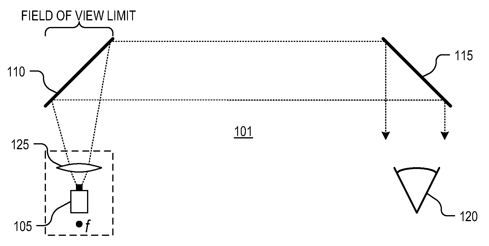
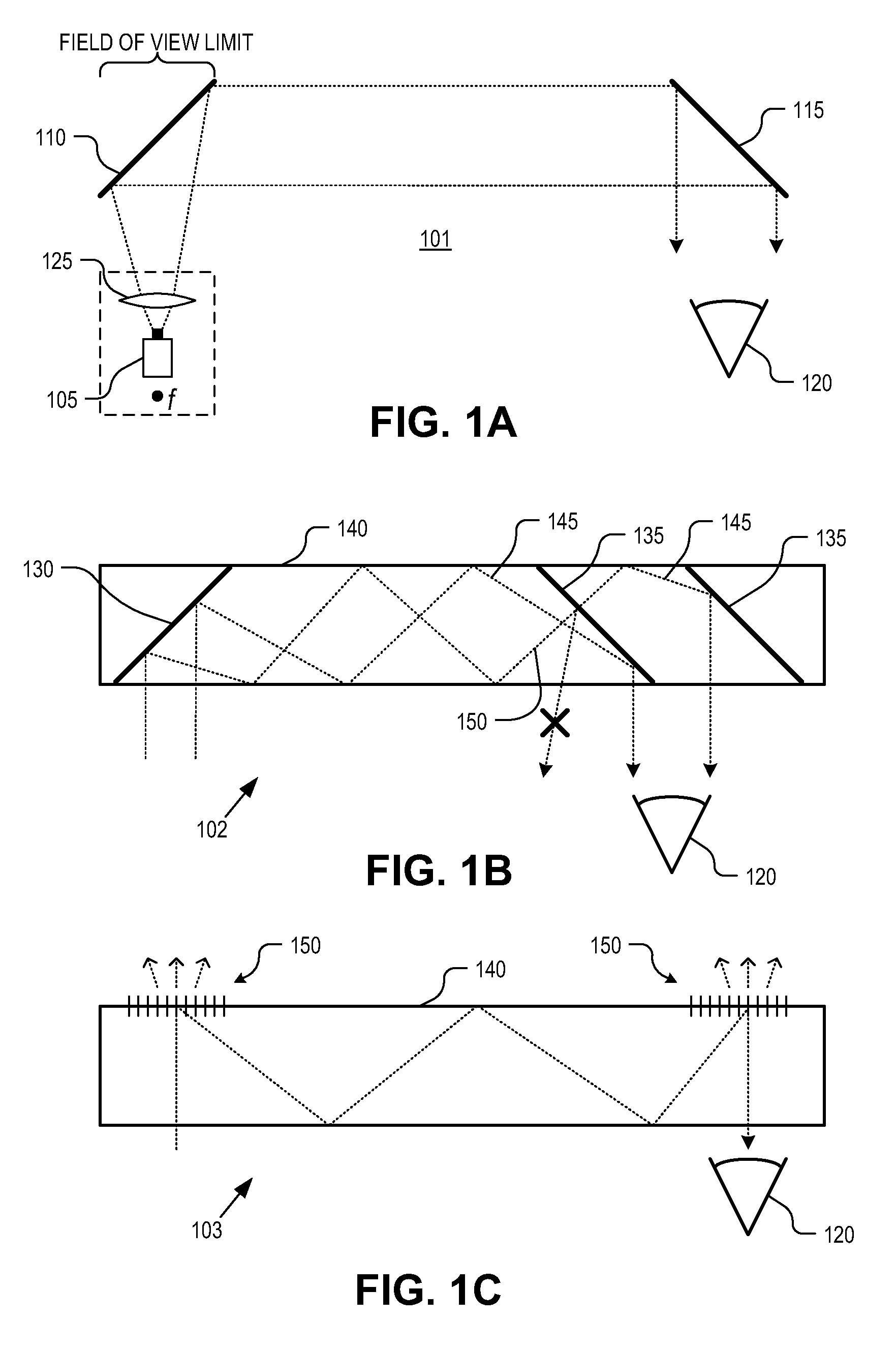
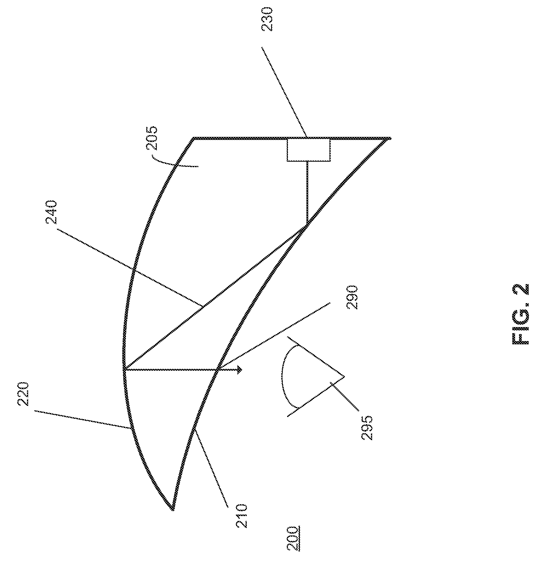
[0016]Embodiments of an apparatus, system and method to utilize a waveguide having two non-parallel surfaces are described herein. In the following description numerous specific details are set forth to provide a thorough understanding of the embodiments. One skilled in the relevant art will recognize, however, that the techniques described herein can be practiced without one or more of the specific details, or with other methods, components, materials, etc. In other instances, well-known structures, materials, or operations are not shown or described in detail to avoid obscuring certain aspects.

[0017]Reference throughout this specification to “one embodiment” or “an embodiment” means that a particular feature, structure, or characteristic described in connection with the embodiment is included in at least one embodiment of the present invention. Thus, the appearances of the phrases “in one embodiment” or “in an embodiment” in various places throughout this specification are not nec...


PUM


Abstract

An image waveguide includes first and second surfaces being non-parallel and opposite to each other. The image waveguide receives input light from an image source along an optical path disposed at least partially between the first and second surfaces. The first reflective surface receives and reflects light from the image source to the second reflective surface. The image waveguide further includes an out-coupling region included in the first reflective surface. The second reflective surface receives and reflects light from the first reflective surface to the out-coupling region to pass light out of the waveguide.

Description

TECHNICAL FIELD[0001]This disclosure relates generally to the field of optics, and in particular but not exclusively, relates to near-to-eye optical systems.BACKGROUND INFORMATION[0002]A head mounted display (HMD) is a display device worn on or about the head. HMDs usually incorporate some sort of near-to-eye optical system to display an image within a few centimeters of the human eye. Single eye displays are referred to as monocular HMDs while dual eye displays are referred to as binocular HMDs. Some HMDs display only a computer generated image (CGI), while other types of HMDs are capable of superimposing CGI over a real-world view. The former type of HDM is often referred to as virtual reality (VR) while latter type of HMD is often referred to as augmented reality (AR) because the viewer's image of the world is augmented with an overlaying CGI, also referred to as a heads-up display (HUD).[0003]HMDs have numerous practical and leisure applications. Aerospace applications permit a ...

Claims


Application Information

Patent Timeline
IPC IPC(8): G02B27/14
CPCG02B5/30G02B2027/0132G02B27/0172
Inventor KELLY, DANIEL G.
Owner GOOGLE LLC
Why Eureka
Try Eureka