
Optics for an extended depth of field

a technology of depth of field and optical system, applied in the field of digital imaging, can solve the problems that the psf of the resulting optical system may still vary from the ideal, and achieve the effect of improving the mtf of all images

Inactive Publication Date: 2012-10-23
NANCHANG O FILM OPTICAL ELECTRONICS TECH CO LTD
View PDF58 Cites 2 Cited by
  • Summary
  • Abstract
  • Description
  • Claims
  • Application Information

AI Technical Summary

Benefits of technology

The solution results in images that are substantially free of aberrations for all objects within the field, significantly increasing the depth of field compared to prior art cameras, ensuring improved image quality across a broader range of object distances.

Problems solved by technology

The PSF of the resulting optical system may still vary from the ideal due to focal variations and aberrations.

Method used

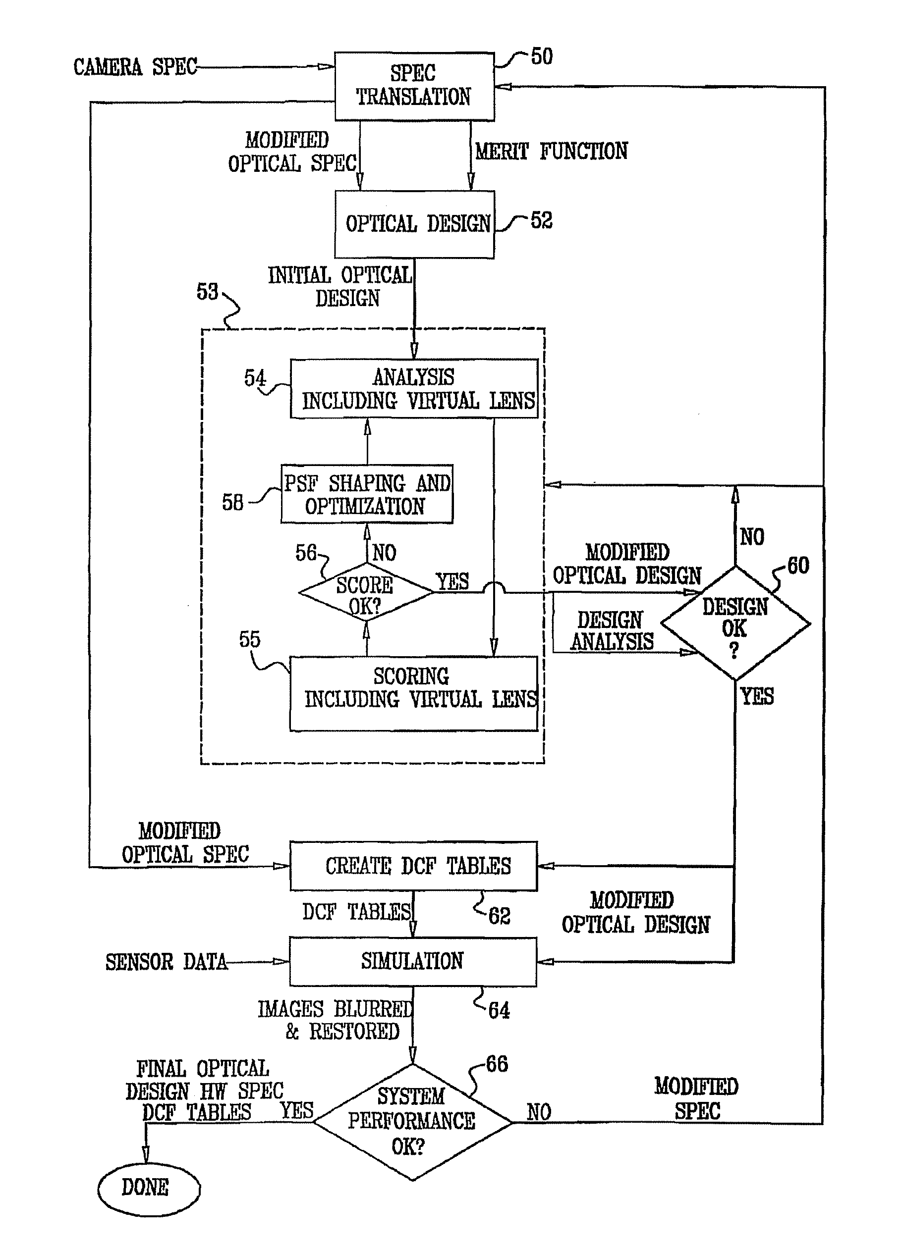
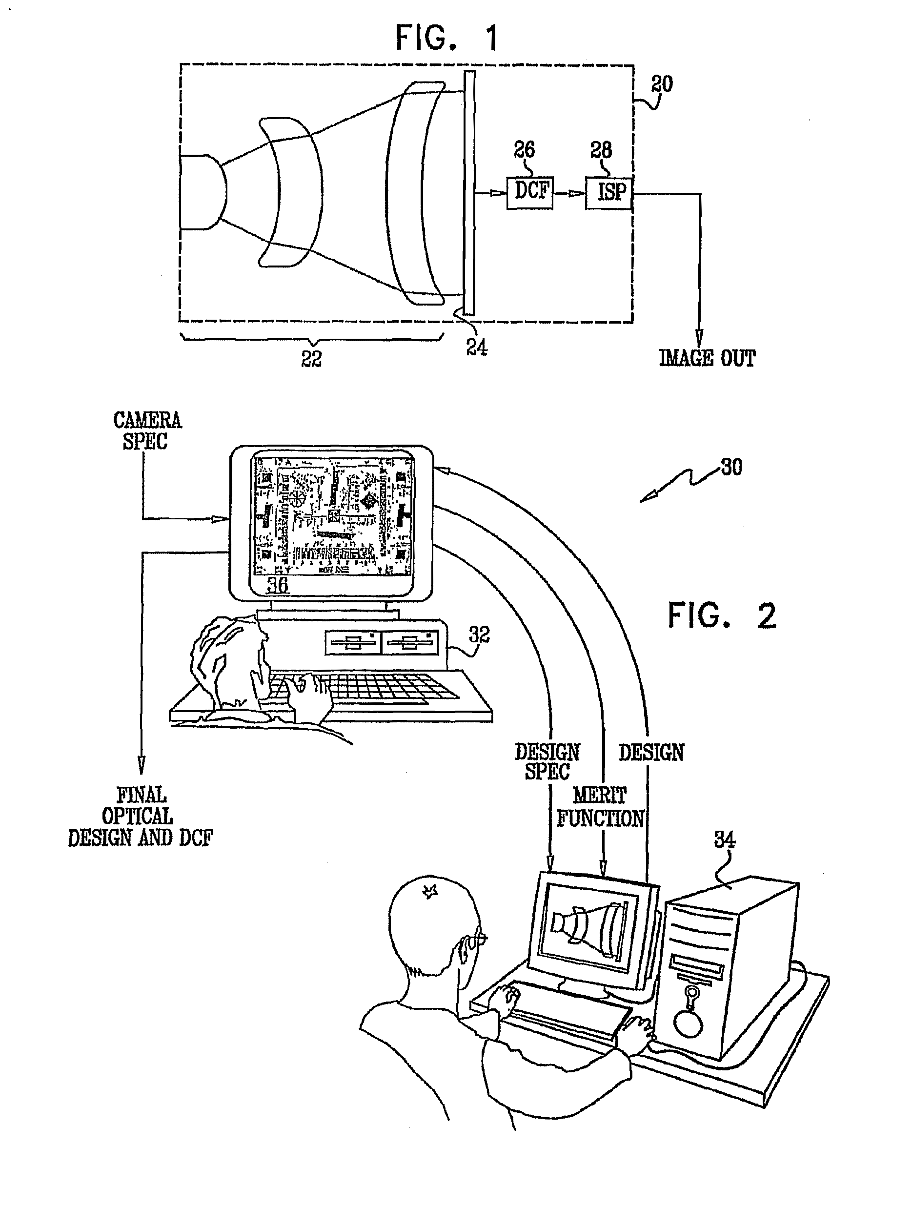
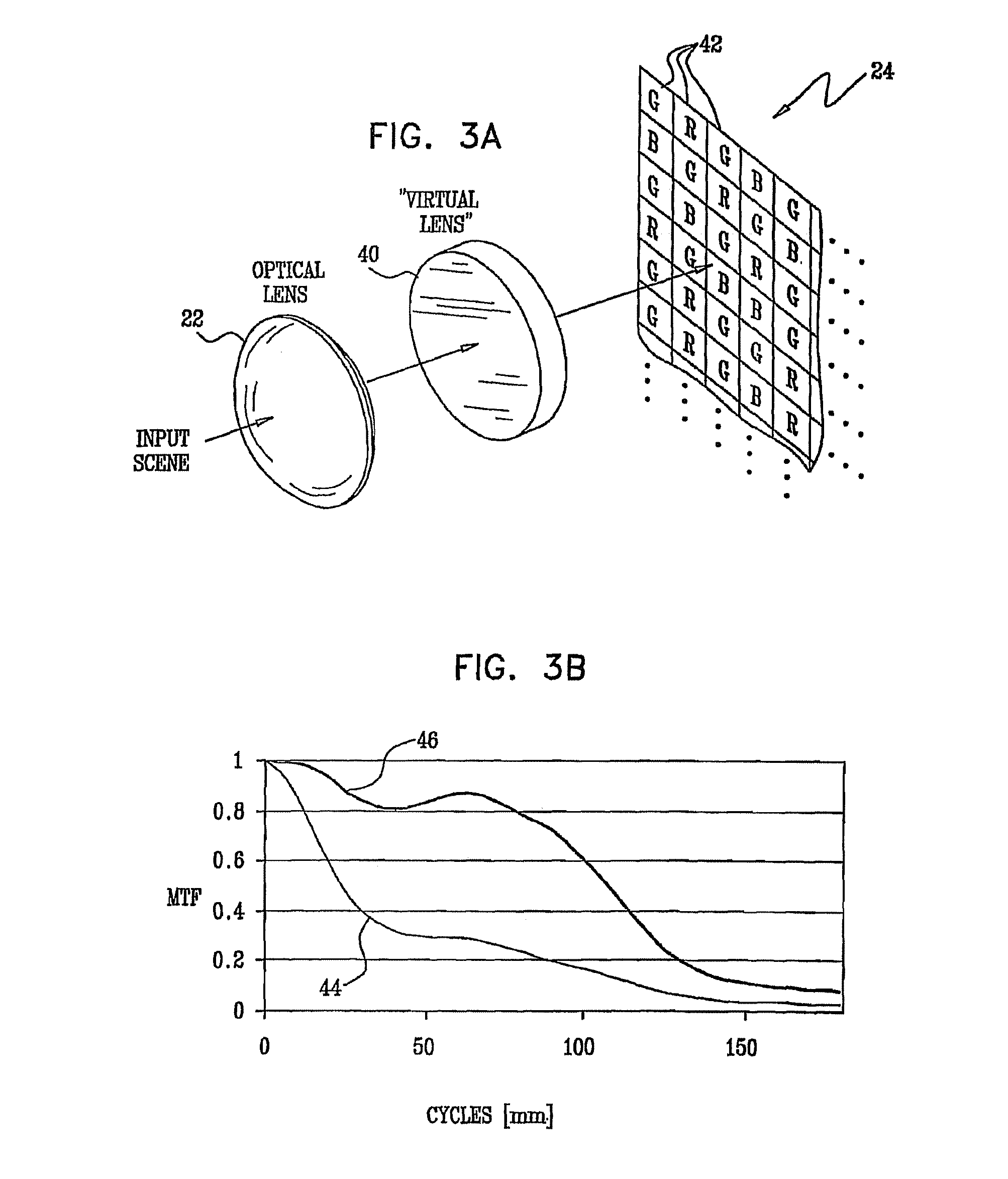

Image

  • Optics for an extended depth of field
  • Optics for an extended depth of field
  • Optics for an extended depth of field

Examples


Embodiment Construction

Definitions

[0061]The following is a non-exhaustive list of technical terms that are used in the present patent application and in the claims. Although these terms are used herein in accordance with the plain meaning accorded the terms in the art, they are listed below for the convenience of the reader in understanding the following description and the claims.[0062]Pitch of a detector array refers to the center-to-center distance between elements of the array.[0063]Cylindrical symmetry describes a structure, such as a simple or compound lens, which has an optical axis such that the structure is invariant under rotation about the optical axis for any and all angles of rotation.[0064]Point spread function (PSF) is the impulse response of an optical system in the spatial domain, i.e., the image formed by the system of a bright point object against a dark background.[0065]Extent of the PSF is the full width at half maximum (FWHM) of the PSF.[0066]Optical transfer function (OTF) is the tw...


PUM


Abstract

An optical imaging assembly having cylindrical symmetry, comprising a plurality of lenses having surfaces with curvatures and spacings between the surfaces, such that an optical image formed by the plurality of lenses has a defocus aberration coefficient greater than 0.1 at a focal plane of the assembly.

Description

CROSS-REFERENCE TO RELATED APPLICATIONS[0001]This application is a continuation of U.S. patent application Ser. No. 12 / 093,394, filed Nov. 11, 2008, now U.S Pat. No. 7,773,316 in the National Stage of PCT Patent Application PCT / IL2006 / 001294, which was filed Nov. 9, 2006, claiming the benefit of U.S. Provisional Patent Application 60 / 735,441, filed Nov. 10, 2005. The PCT Patent Application PCT / IL2006 / 001294 is a continuation-in-part of U.S. patent application Ser. No. 10 / 541,967, now U.S. Pat. No. 7,627,193, filed June 23, 2006, in the National Stage of PCT Patent Application PCT / IL04 / 00040, which was filed Jan. 15, 2004, claiming the benefit of U.S. Provisional Patent Application 60 / 440,561, filed Jan. 16, 2003. The PCT Patent Application PCT / IL2006 / 001294 is also a continuation-in-part of U.S. patent application Ser. No. 11 / 278,255, now abandoned, filed Mar. 31, 2006. The entireties of all of the above-referenced related applications are incorporated herein by reference.FIELD OF T...

Claims


Application Information

Patent Timeline
Patent Type & Authority Patents(United States)
IPC IPC(8): G02B27/00
CPCG02B27/0012H04N5/217H04N5/225H04N5/2254G06F17/50G06F30/00H04N23/81H04N25/615H04N25/61H04N23/00
Inventor ALON, ALEXALON, IRINABEZDIN, HAIM
Owner NANCHANG O FILM OPTICAL ELECTRONICS TECH CO LTD
Learn More