Pump control using overpressure source

a technology of overpressure source and pump, which is applied in the direction of machines/engines, liquid fuel engines, positive displacement liquid engines, etc., can solve the problems of overpressure of the oil pump, the output of the pump exceeds the output required by the engine, and the output pressure of the pump changes, so as to reduce the output pressure of the pump, and increase the force of the biasing spring

Active Publication Date: 2012-10-30
HANON SYST EFP CANADA LTD
View PDF17 Cites 6 Cited by
  • Summary
  • Abstract
  • Description
  • Claims
  • Application Information

AI Technical Summary

Benefits of technology

[0012]It is an object of the present invention to provide a novel rotary positive displacement pump which obviates or mitigates at least one disadvantage of the present invention.
[0013]According to a first aspect of the present invention, there is provided a rotary positive displacement pump for supplying pressurized working fluid to a driving device, the pump comprising: a biasing spring acting against a force created by the pressurized working fluid from the outlet port of the pump to reduce the output pressure of the pump; and a region in the pump wherein the pressure of the working fluid is greater than the pressure of the working fluid at the outlet port of the pump, the greater pressure working fluid creating a force which augments the force of the biasing spring.
[0014]Preferably a pump body having a rotor chamber, a pump inlet communicating with an inlet port and a pump outlet communicating with the outlet port; a rotor set being rotatable in the rotor chamber to supply pressurized working fluid from the inlet port to the outlet port; and a control valve comprising: a piston moveable in a bore, the piston having a head and a shaft, the head of the piston being exposed to pressurized working fluid from the pump outlet which creates a force on the piston to urge the piston along the bore to a first position to expose a discharge port in fluid communication with a low pressure working fluid sink to permit pressurized working fluid to move to the low pressure working fluid sink to reduce the output pressure of the pump; the biasing spring acting against the shaft of the piston to bias the piston to a second position wherein the discharge port is blocked by the head of the piston to prevent pressurized working fluid to move to the low pressure working fluid sink; and a chamber located about the shaft of the piston adjacent the head, the chamber being in fluid communication with the higher pressure source of working fluid to receive pressurized working fluid therefrom to create a force on the piston to also bias the piston towards the second position.
[0015]Also preferably, the pump is a variable displacement vane pump with a control slide moveable to vary the displacement of the pump and wherein a control chamber is formed against the control slider and receives pressurized working fluid from the outlet of the pump, the pressurized working fluid creating a force to move the control slider to a position of reduced displacement, the biasing spring biasing the control slider toward a position of maximum displacement and a second chamber formed against the control slider receives pressurized working fluid from the region of higher pressure and creates a force on the control slider to augment the biasing force of the biasing spring.
[0016]The present invention provides a rotary positive displacement pump which employs a higher pressure source of working fluid to augment the force of a biasing spring in a control mechanism. A biasing spring with a lower spring force can thus be employed in the control mechanism, resulting in a pump pressure output characteristic which can more closely match the operating speed varying working fluid requirements for devices supplied by the pump.

Problems solved by technology

The lubrication system of the engine can be viewed as a fixed size orifice, and thus changes in the output volume of the pump result in changes in the output pressure of the lubrication oil.
Because the volumetric displacement of the oil pump must be sufficient to meet the engine lubrication requirements at relatively low pump operating speeds, generally the output of the oil pump is too high at higher operating speeds and the pressure relief valve allows some of the output of the pump to be returned to the low pressure sink.
While such fixed displacement pump systems are widely employed, they do suffer from some disadvantages.
In particular, due to limitations in the operation of the pressure relief valve, the output of the pump exceeds the output required by the engine at many points of those expected operating conditions.
When the pump output exceeds the engine operating requirements, engine energy is being wasted pressurizing lubrication oil which is not needed by the engine.
While variable displacement pumps tend to provide more energy efficient results, they also suffer from similar problems to those of fixed displacement pumps in meeting, but not exceeding, the pressure requirements of a prime mover which change with the operating speed of the prime mover and pump.

Method used


Image

  • Pump control using overpressure source
  • Pump control using overpressure source
  • Pump control using overpressure source

Examples


Embodiment Construction

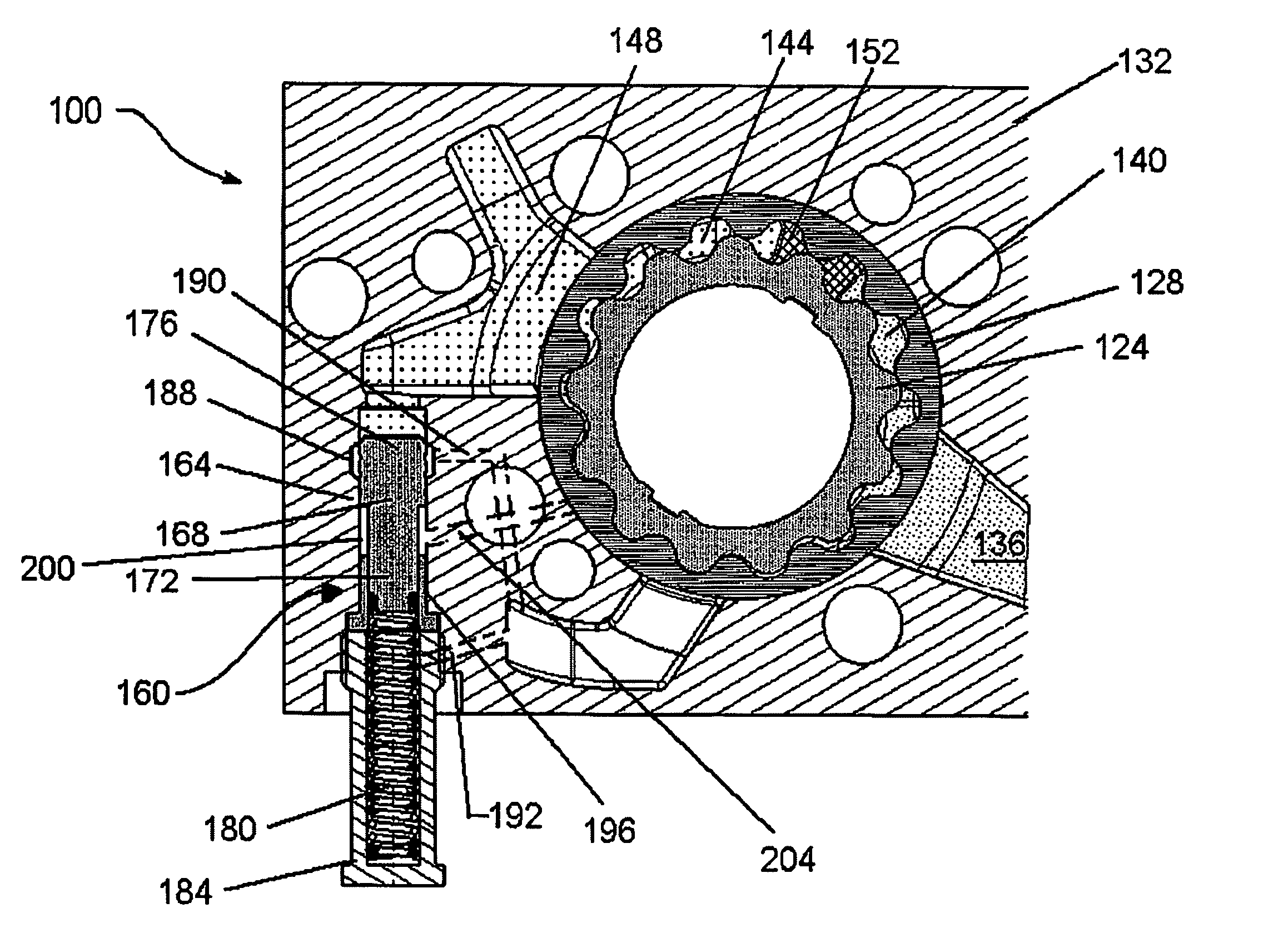
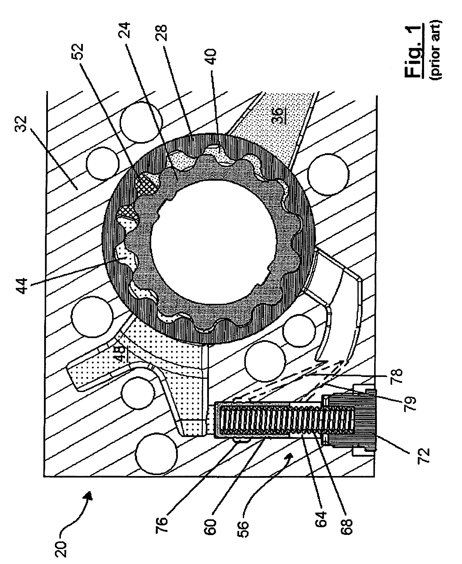
[0025]Before describing the present invention, a prior art rotary positive displacement pump will first be described to assist in better understanding the present invention. Accordingly, a prior art internal-external gear pump is indicated at 20 in FIG. 1. Pump 20 includes a rotor comprising a driven inner rotor 24 and an outer rotor 28 which rotate within a rotor chamber in pump body 32.

[0026]Pump body 32 defines a pump inlet 36, which supplies unpressurized working fluid from a connected source of working fluid to be pressurized, to the pump chambers defined between the lobes of inner rotor 24 and outer rotor 28 through an inlet port 40.

[0027]The pressurized working fluid exits the pump chambers defined between the lobes of inner rotor 24 and outer rotor 28 via an outlet port 44, and exits pump 20 through a pump outlet 48.

[0028]Inlet port 40 and outlet port 48 are separated from each other by a pair of sealing lands 52 (only one of which is visible in FIG. 1) which inhibit leakage...


PUM


Abstract

A rotary positive displacement pump employs the higher pressure available at a region within the rotor chamber after the outlet port to augment the force of a biasing spring in a control system. A biasing spring with a lower spring force can thus be employed in the control system, resulting in a pump pressure output characteristic which can more closely match the operating speed varying working fluid requirements for devices supplied by the pump.

Description

FIELD OF THE INVENTION[0001]The present invention relates to rotary positive displacement pumps and the like. More specifically, the present invention relates to a system and method for controlling the output of rotary positive displacement pumps.BACKGROUND OF THE INVENTION[0002]Rotary positive displacement pumps, such as vane pumps or internal-external gear pumps are well known and are widely used in a variety of environments. As used herein, the term rotary positive displacement pump is intended to comprise vane pumps, gear and crescent pumps, internal-external gear pumps, etc. Further, internal-external gear pumps include pumps which have a rotor set that includes an outer rotor having a given number of lobes and an inner rotor with at least one less lobe. The inner rotor is driven and rotates within and with the outer rotor and the lobes of the inner rotor moving into and out of the lobes of the outer rotor form a series of pump chambers. Examples of internal-external gear pumps...

Claims


Application Information

Patent Timeline
Patent Type & Authority Patents(United States)
IPC IPC(8): F04B49/00
CPCF04C2/102F04C2/3442F04C14/226Y10T137/7905
Inventor SHULVER, DAVID R.WILLIAMSON, MATTHEWCIOC, ADRIAN C.
Owner HANON SYST EFP CANADA LTD
Why Eureka
Try Eureka