Non-gel based two-dimensional protein separation multi-channel devices

a two-dimensional protein and multi-channel technology, applied in the direction of peptides, fluid pressure measurement, liquid/fluent solid measurement, etc., can solve the problems of difficult automation, labor-intensive 2d-page method, complex proteins, etc., and achieve the effect of preventing denaturation of proteins

Active Publication Date: 2012-10-30
IND ACADEMIC CORP FOUND YONSEI UNIV
View PDF2 Cites 2 Cited by
  • Summary
  • Abstract
  • Description
  • Claims
  • Application Information

AI Technical Summary

Benefits of technology

[0027]As can be seen from the foregoing, it is possible to separate the proteins according to pI and molecular weight, be safe from denaturation of the protein in the process of protein separation, and automatically remove an ampholyte used for pI-based separation. When the separated and recovered proteins are subjected to enzymatic hydrolysis treatment, it is possible to directly use protein identification by applying nanoflow liquid chromatography-electrospray ionization-tandem mass spectrometry (LC-ESI-MS-MS) to peptide analysis.

Problems solved by technology

Meanwhile, the proteins are very complicated due to various properties such as a molecular weight, isoelectric point (pI), hydrophilicity, hydrophobicity, and so on.
This method is a one-dimensional separation method that is widely used in the field of separating and identifying proteins in order of molecular weight and in the process of separating and identifying simple proteins, and has a problem in that the proteins have a tertiary structure denatured in an SDS solution, or are confined in the gel.
However, the 2D-PAGE is a labor-intensive method, is difficult to automate, and is limited in detection sensitivity and dynamic range.
Further, separating the proteins without denaturation is difficult in the 2D-PAGE because the SDS solution is used to separate the proteins, which results in separation of the proteins in the denatured state, and recovering the sample is not easy because the separated proteins are also confined in a gel matrix.
Further, despite the capability of processing the small quantity of protein samples due to the intracapillary separation and the high sensitivity, the CIEF is limited in its separation capability to process complicated protein mixtures such as proteome.
However, due to protein chain breakdown occurring when the proteins pass through the chromatography column, protein loss within the chromatography column, and so on, it is difficult to apply the CIEF-CGE to the proteins.
As such, sample analysis is difficult in the CIEF-RPLC due to inhibition of ions in the solution without previous removal of the ampholyte.
However, although the CIEF-RPLC is used to separate the proteins, denaturation of the proteins cannot be avoided due to use of an organic solvent during the RPLC separation, and the CIEF-RPLC cannot be applied to the separation of the proteins having large molecular weight.
However, the separation method using the AFIFFF is not very high in separation capability, and has difficulty in carrying out the separation on the basis of various properties of the protein.
5789-5798] has an advantage in that the proteins can be separated in two dimensions without using the gel, and a disadvantage in that an amount of separable proteins has no choice but is restricted due to a limitation of a capacity of the capillary in the event of the primary isoelectric focusing the capillary.
This results in a problem that allows the separated fractions to be mixed again, and causes contamination of the fractions.
In the case of the CIEF-HF FIFFF, because a maximum amount of the proteins that can be injected at once is about 40 μg, there is the limitation of a capacity to some extents to process a large amount of proteome samples.

Method used


Image

  • Non-gel based two-dimensional protein separation multi-channel devices
  • Non-gel based two-dimensional protein separation multi-channel devices
  • Non-gel based two-dimensional protein separation multi-channel devices

Examples


example 1

Manufacturing of Protein Separating Apparatus

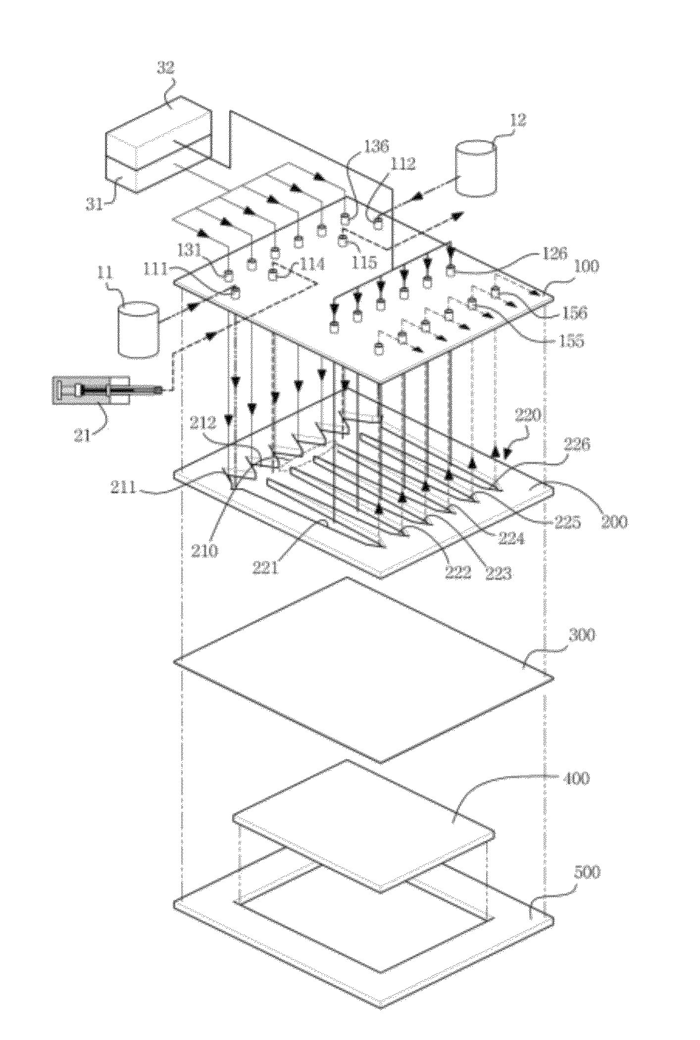
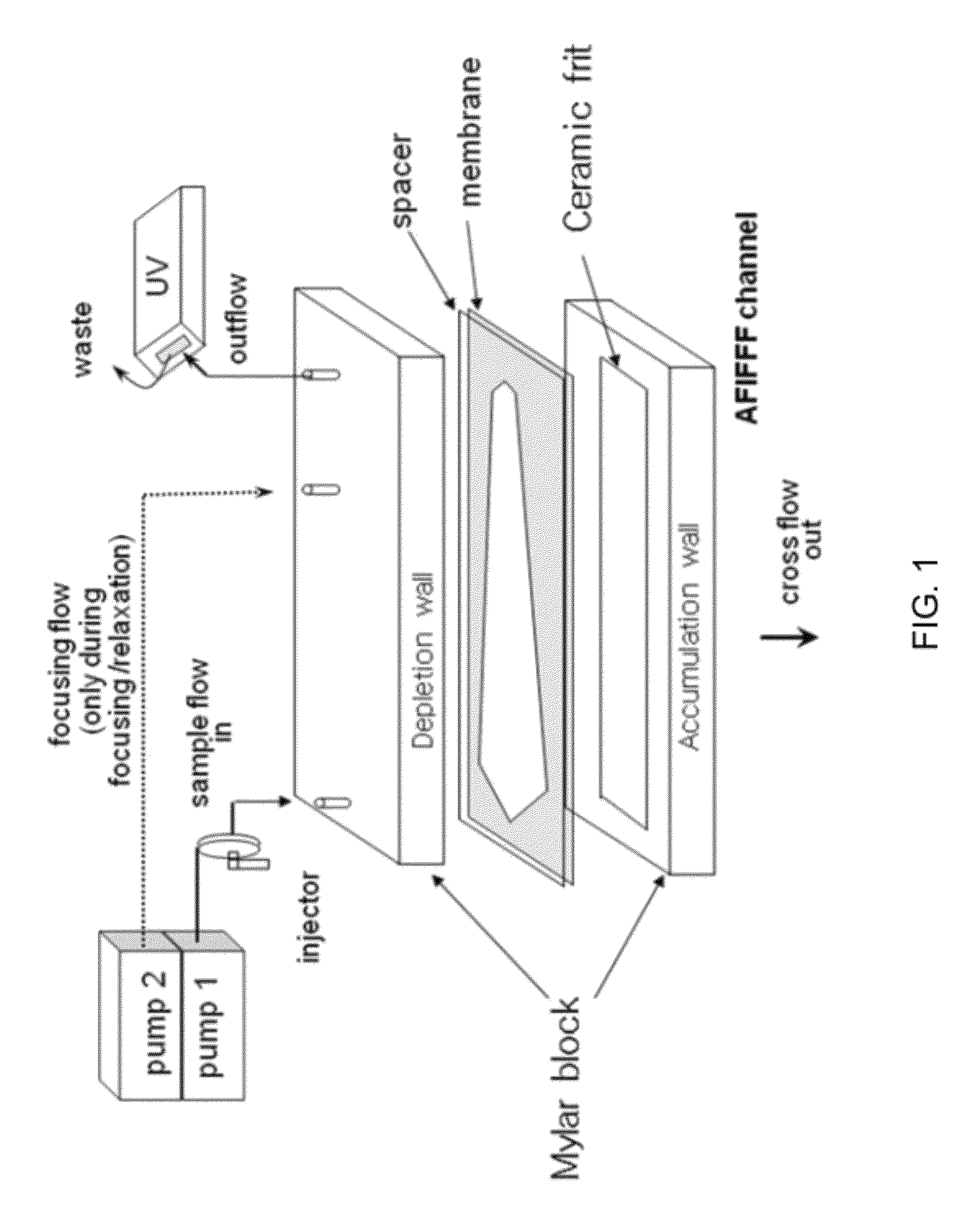
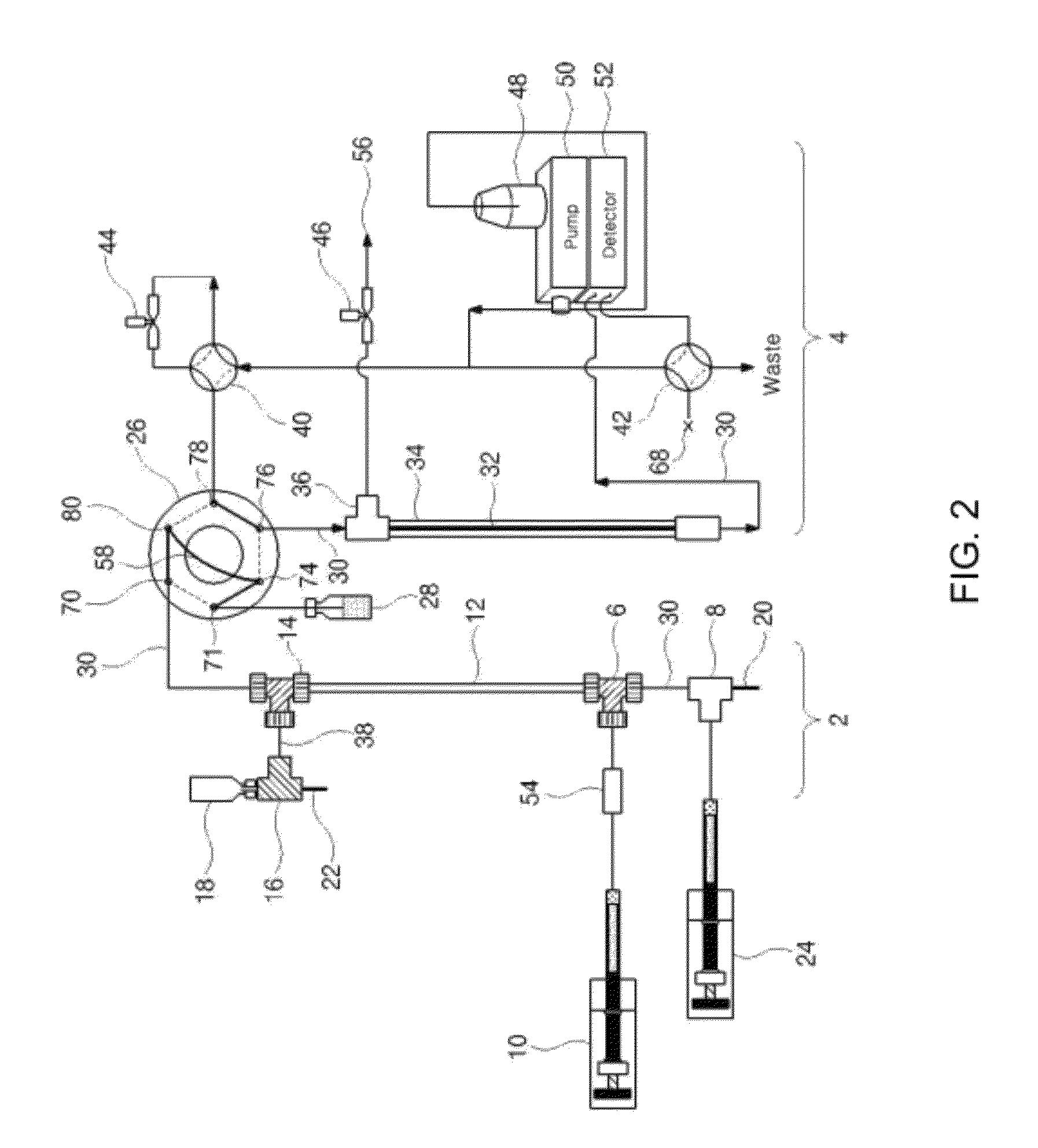
[0110]In order to connect the multiple channels with the tubes, a total of 22 connectors, i.e. six inlets and six outlets, six connectors for discharging the fluid from the six focusing flow parts, two connectors for inflow and outflow of the samples and two connectors for connection with the electrodes within the isoelectric focusing section, employed nuts of the same PEEK (available from Upchurch Scientific, USA), as shown in FIG. 4. The six Teflon tubes of the channel inlets were connected with the first feed pump using a 6-way manifold (having one inlet and six outlets) (available from Upchurch Scientific, USA). The first feed pump employed an HPLC pump. Similarly, the focusing flow inlets for the focusing flow (the six inlets between the channel inlets and the channel outlets) were connected with the second feed pump using Teflon tubes and a 6-way manifold in the same fashion as the channel inlets. The six connectors of the channel o...

example 2

Separation of Single Protein Standard Substance Using Isoelectric Focusing Apparatus

[0114]In order to check an isoelectric focusing effect in the protein separating apparatus (isoelectric focusing-flow field-flow fractionation multi-channel apparatus) manufactured according to the Example 1, a sample, cytochrome-c (12.7 kDa, pI 10.25), was separated by itself, and was mixed with an excessive amount (30 μg) of ampholyte solution in order to visually check a red color of the sample itself. The mixture was injected to the multiple channels using the syringe pump, and then was subjected to isoelectric focusing under the conditions of 3 min, 2 kV, and 1.25 mA.

[0115]As shown in FIG. 6, it can be seen that protein bands are indicated by narrow lines. In FIG. 6, the left side is an anode side, and the right side is a cathode side.

[0116]Further, the isoelectrically focused protein samples become electrically neutral between the opposite electrodes, are no longer electrophoresed toward the el...

example 3

Isoelectric Focusing Difference of Single Protein Caused by Voltage Change in the Event of Isoelectric Focusing

[0117]The efficiency of the isoelectric focusing separation depending on a difference in applied voltage in the isoelectric focusing process using the protein separating apparatus of the Example 1 was examined. A sample, carbonic anhydrase (29 kDa, pI 5.8), was injected at an amount of 1 μg, and was subjected to the isoelectric focusing under the condition that the applied voltage was 1.0 kV, 2.0 kV, 2.5 kV, and 3.0 kV. The results of comparing the conditions of 1.0 kV and 3.0 kV are shown in FIG. 7.

[0118]As shown in FIG. 7, when the applied voltage was 3.0 kV, a sample of carbonic anhydrase was focused within a given time, and was separated only in channel #3. In contrast, when the applied voltage was 1.0 kV, the protein was separated in channels #2, #3 and #4. This means that, when the protein is subjected to the isoelectric focusing, the protein is widely spread without ...


PUM

PropertyMeasurementUnit
distanceaaaaaaaaaa
depthaaaaaaaaaa
molecular weightaaaaaaaaaa

Abstract

Provided is a multi-channel apparatus for non-gel based two-dimensional protein separation. One or more flat channels are arranged in parallel and have an isoelectric focusing section for primarily separating proteins from protein samples according to isoelectric point (pI) and a flow field-flow fractionation section for secondarily separating the primarily separated proteins according to molecular weight, thereby making it possible to simultaneously separate the proteins in multiple channels, to increase a protein separation speed, and to overcome limitation to sample injection due to an increase in channel volume. The apparatus can separate the proteins according to pI and molecular weight, be safe from denaturation of the protein in the process of protein separation, automatically remove an ampholyte used for pI-based separation, and separately detecting the separated proteins to identify the proteins using nanoflow liquid chromatography-electrospray ionization-tandem mass spectrometry (LC-ESI-MS-MS).

Description

CROSS-REFERENCE TO RELATED APPLICATIONS[0001]This application is a 35 U.S.C §371 of PCT Application Serial No. PCT / KR2009 / 002742, filed May 25, 2009, currently pending, entitled “Non-gel Based Two-dimensional Protein Separation Multi-channel Devices,” which claims priority to Korean Patent Application No. 10-2008-0048842 filed May 26, 2008, entitled “Non-gel Based Two-dimensional Protein Separation Multi-channel Devices,” which are each incorporated herein by reference in their entirety.TECHNICAL FIELD[0002]The present invention relates to a non-gel based two-dimensional protein separation multichannel devices, and more particularly, to a non-gel based two-dimensional protein separation multichannel devices including one or more flat channels arranged in parallel which include an isoelectric focusing section for primarily separating proteins from protein samples according to isoelectric point (pI) and a flow field-flow fractionation section for secondarily separating the primarily s...

Claims


Application Information

Patent Timeline
Patent Type & Authority Patents(United States)
IPC IPC(8): B01D57/02
CPCG01N27/44773G01N35/1097G01N27/44782G01N27/44795G01N30/0005G01N2030/003C07K1/285G01N33/68
Inventor MOON, MYEONG HEEKIM, KI HUN
Owner IND ACADEMIC CORP FOUND YONSEI UNIV
Why Eureka
Try Eureka