Control method of information processing device and information processing device

a control method and information processing technology, applied in the field of information processing technology, can solve the problems of increasing the cost of mounting the inability to neglect the installation of dedicated debug signal wires, and the inability to mount signal wires between devices, so as to achieve the effect of not increasing costs

Inactive Publication Date: 2012-10-30
FUJITSU LTD
View PDF11 Cites 4 Cited by
  • Summary
  • Abstract
  • Description
  • Claims
  • Application Information

AI Technical Summary

Benefits of technology

[0012]It is an object of the present invention to provide a technology for capable of realizing exact debug using the debug function of hardware without increasing costs.
[0013]It is another object of the present invention to provide a technology capable of realizing the debug of system behavior highly depending on an operational timing without requiring hardware, such as an extra dedicated signal wire and the like.
[0026]The present invention realizes the transmission of information between devices by using the signal wire for a redundant bit, such as this ECC and the like. Since an ordinary bus is provided with this signal wire for a redundant bit, there is no need to install a dedicated debug signal wire, thereby reducing the manufacturing cost of a debug-related function.
[0028]Since a correctable error is simply caused by operating a redundant bit, essential transmitting data, a transmitting timing and the like are not affected at all. Specifically, a debug function provided in each device can be controlled by operating redundant bits without disturbing the normal operating state of the system.

Problems solved by technology

However, since today the integration density of semi-conductor devices constituting a device is improved, and the mounting cost of signal wires between devices becomes relatively high and is increasing, a cost for installing a dedicated debug signal wire, which is not used at all in a normal operation, between devices cannot be neglected.
However, in this case, the normal running operation of the system is disturbed by the execution of this control command and it becomes disadvantageous when analyzing a system behavior highly depending on an operational timing.

Method used


Image

  • Control method of information processing device and information processing device
  • Control method of information processing device and information processing device
  • Control method of information processing device and information processing device

Examples


Embodiment Construction

[0042]The preferred embodiments of the present invention are described in detail below with reference to the drawings.

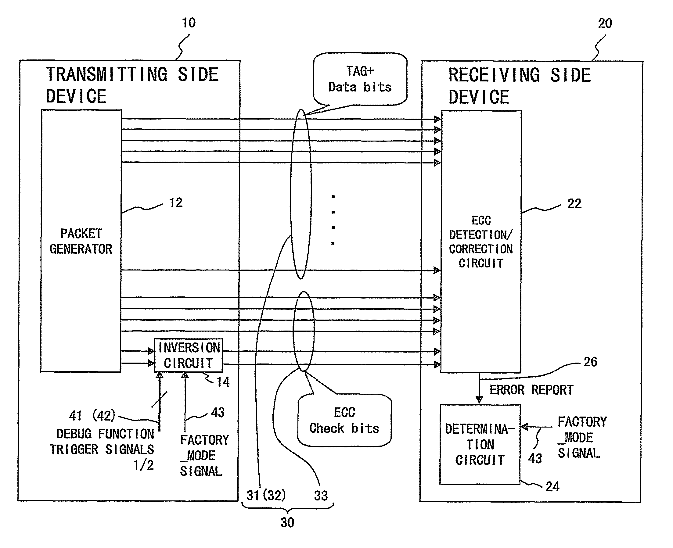
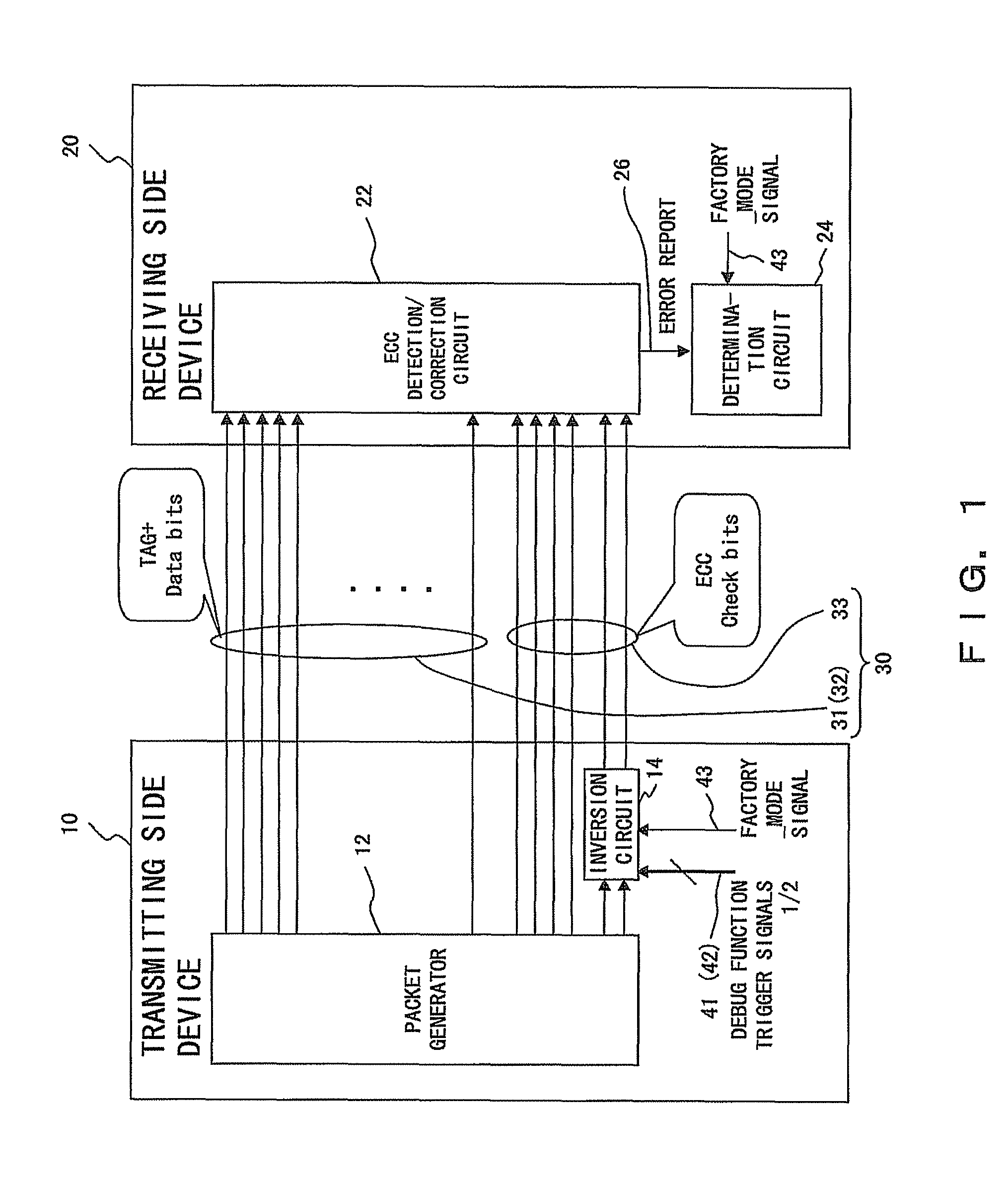
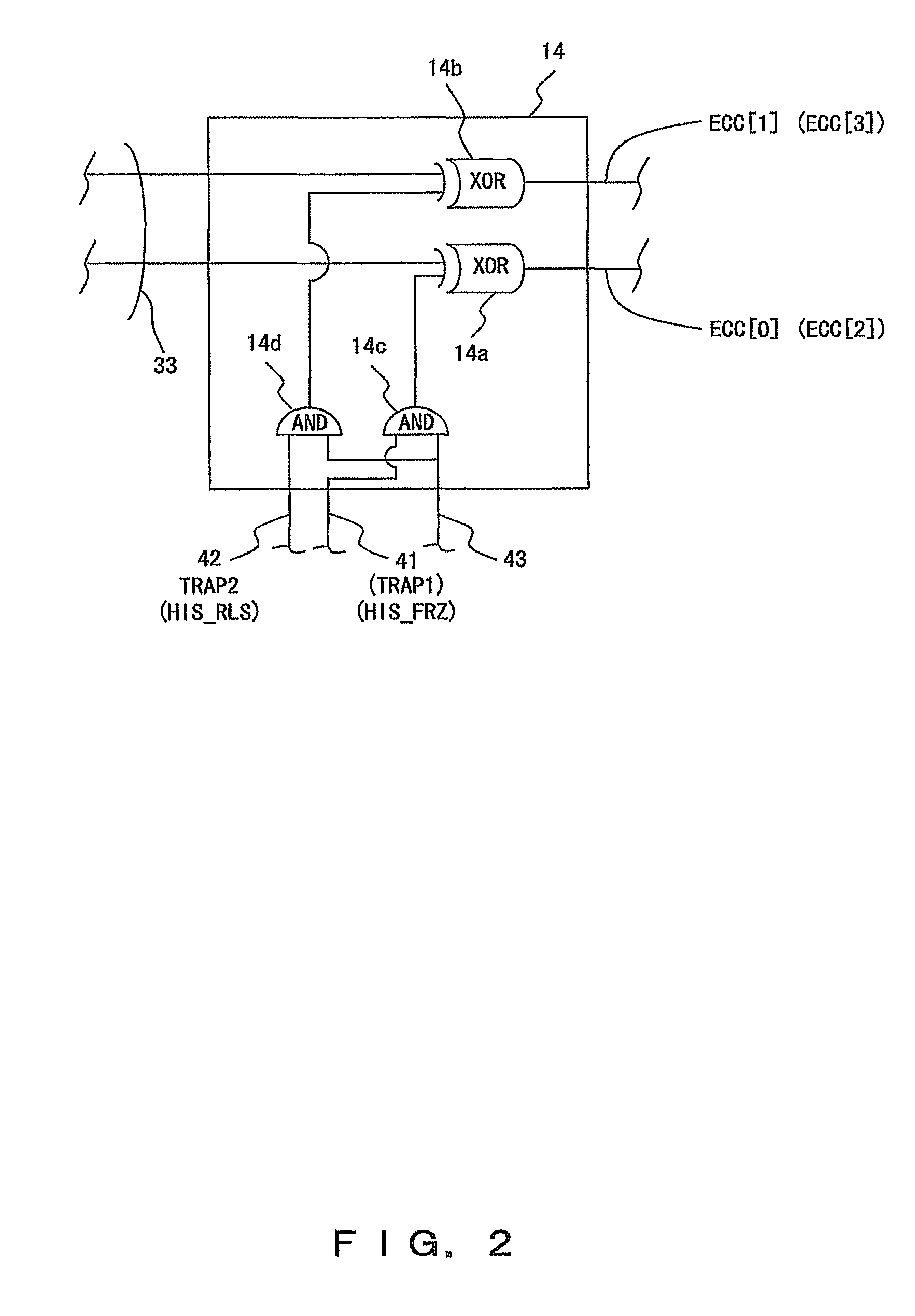
[0043]FIG. 1 is a block diagram showing the configuration example of the information processing device for implementing the control method of the information processing device in one preferred embodiment of the present invention. FIG. 2 is a conceptual drawing exemplifying the information processing system by taking a part of the information processing device in one preferred embodiment of the present invention.

[0044]As exemplified in FIG. 1, the information processing device in this preferred embodiment comprises a transmitting side device 10 and a receiving side device 20.

[0045]Between the transmitting side device 10 and the receiving side device 20, a bus 30 is provided. Data is transferred from the transmitting side device 10 to the receiving side device 20 using this bus 30.

[0046]The bus 30 comprises TAG bits 31, data bits 32 and redundant ECC bits 33 for protec...


PUM


Abstract

A transmitting side device (10) and a receiving side device (20) are connected to each other via a bus (30) comprising TAG bits (31), data bits (32) and error detection / correction ECC bits (33). The transmitting side device (10) uses a redundant bit inversion circuit (14) to invert different bits of the ECC bits (33) corresponding to trigger signals (41&42). In the receiving side device (20), a determination circuit (24), which has received an error report signal (26) from an error detection / correction circuit (22), determines, from the position of an error bit in the ECC bits (33), which one of the trigger signals (41&42) has been transmitted from the transmitting side device (10).

Description

CROSS-REFERENCE TO THE RELATED APPLICATION[0001]This application is a continuation application of an international patent application No. PCT / JP2006 / 303653, filed on Feb. 27, 2006.BACKGROUND OF THE INVENTION[0002]1. Field of the Invention[0003]The present invention relates to information processing technology, for example, a technology effective when applied to debug, performance measurement and the like in the development process, maintenance process and the like of an information processing device.[0004]2. Description of the Related Arts[0005]For example, in the development and maintenance processes of an information processing device, it is necessary to debug in order to trace the cause of an abnormal operation or a failure, to improve performance or the like.[0006]Therefore, history memory for recording an operation history can be provided in a plurality of devices constituting a system, an operation history during a specific period before and after a failure occurs can be recor...

Claims


Application Information

Patent Timeline
Patent Type & Authority Patents(United States)
IPC IPC(8): H03M13/00
CPCH04L1/0042H04L1/0047H04L25/4915G06F11/349
Inventor UNNO, HIDEYUKIUKAI, MASAKIAOKI, NAOZUMI
Owner FUJITSU LTD
Why Eureka
Try Eureka