Dispenser device

a dispenser device and liquid technology, applied in the direction of liquid dispensers, coin-freezing apparatus, containers, etc., can solve the problems of not entirely suitable for dispensing a cosmetic or care product suitable for use on the beach, the dispenser device is relatively complex and expensive, and the thickness of the material is reduced, so as to achieve greater stress, reduce the thickness of the material, and reinforce the top wall strength

Inactive Publication Date: 2012-11-06
LOREAL SA
View PDF18 Cites 0 Cited by
  • Summary
  • Abstract
  • Description
  • Claims
  • Application Information

AI Technical Summary

Benefits of technology

[0007]Between them, these two surfaces leave a clearance which can be selected to be sufficiently narrow, for example less than or equal to 0.5 millimeters (mm), or even about 0.2 mm, so as to prevent sand from penetrating into the inside of the device.
[0030]For equivalent strength, it is thus possible to reduce the thickness of material used, or for equal thickness of material, it is possible to withstand greater levels of stress and to increase rates of manufacturing throughput, for example.

Problems solved by technology

The dispenser devices described in those U.S. patents are not designed to prevent impurities such as grains of sand from penetrating into the inside, and they are not entirely appropriate for dispensing a cosmetic or care product suitable for use on a beach, for example a sunscreen.
Nevertheless, such a dispenser device is relatively complex and expensive to make.

Method used


Image

  • Dispenser device
  • Dispenser device
  • Dispenser device

Examples


Embodiment Construction

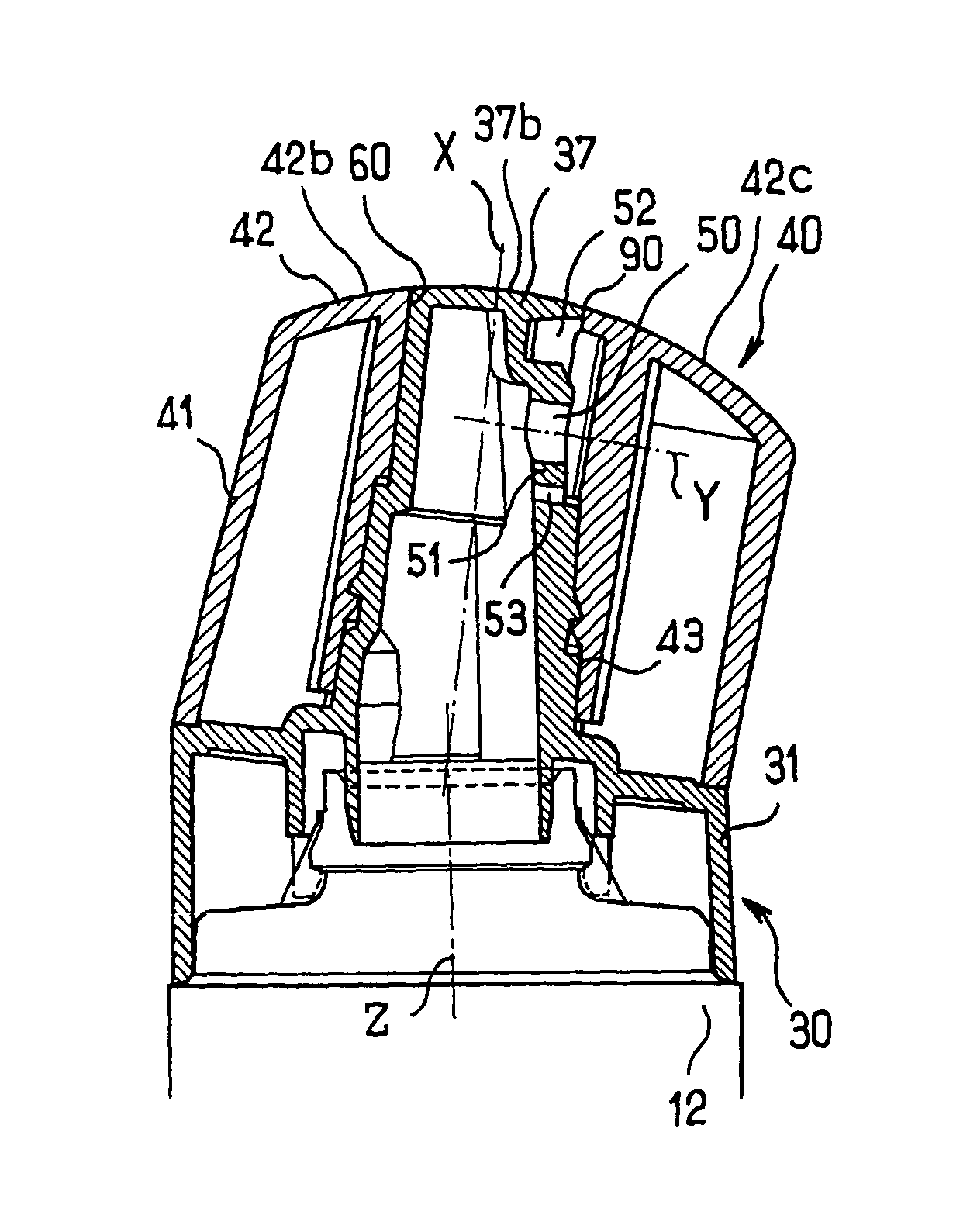
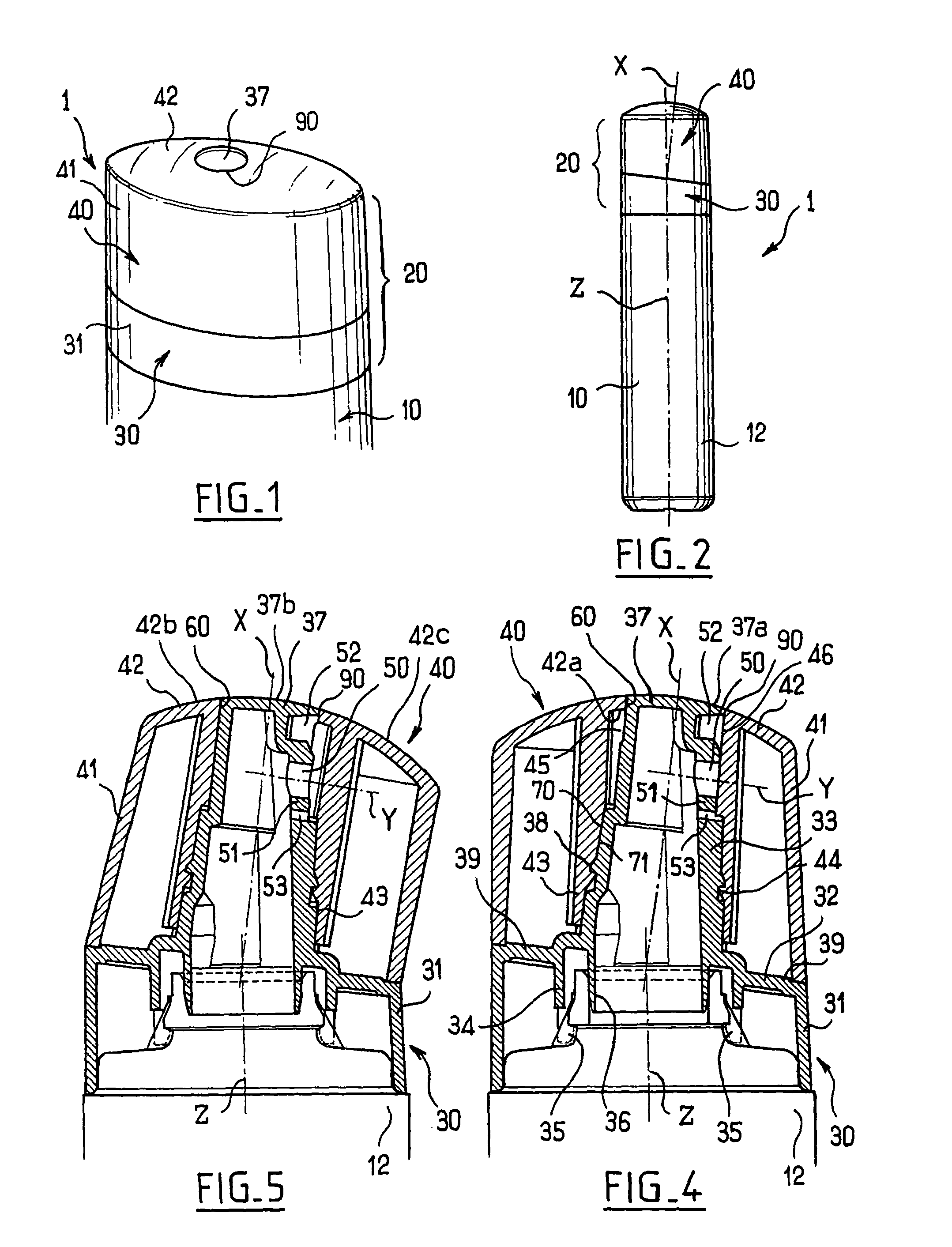
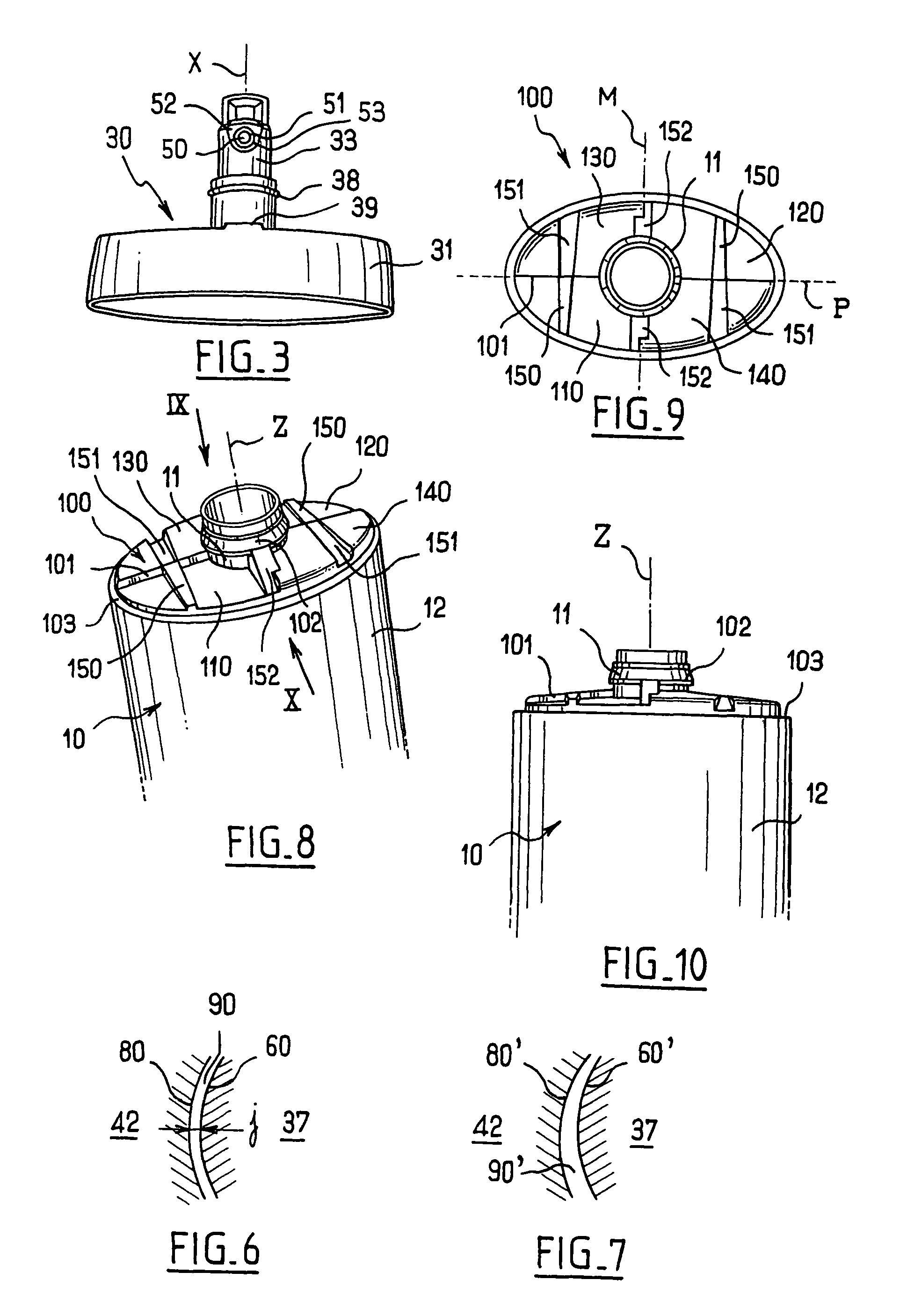
[0042]The packaging and dispenser device 1 shown in the figures comprise a receptacle10 having a neck 11 of axis Z and a dispenser device 20 made up of two parts, namely a first part 30 for fixing on the receptacle 10 by snap-fastening and a second part 40 capable of turning in either direction relative to the first part 30 about a pivot axis X which is at an angle of less than 45° relative to the axis Z in the example described, for example at an angle of a little less than 10°. In the example described, the first and second parts 30 and 40 are made of non-elastomeric plastics materials of different colors.

[0043]The receptacle 10 may comprise a body 12 of oblong cross-section, and specifically of elliptical cross-section in the example described.

[0044]As can be seen in FIGS. 4 and 5 in particular, the first part 30 comprises a tubular outer skirt 31 designed to occupy a position in which it extends the outer surface of the receptacle 10.

[0045]A transverse wall 32 extending generall...


PUM


Abstract

A dispenser is provided including a first part for fixing on a receptacle and a second part suitable for turning relative to the first part between a dispensing position in which substance contained in the receptacle can leave the device through a dispenser orifice opening out directly to the outside, and a closed position in which substance is prevented from passing from the receptacle to the dispenser orifice, wherein the dispenser orifice is formed between two surfaces belonging respectively to said two parts.

Description

CROSS-REFERENCE TO RELATED APPLICATIONS[0001]This application claims priority from French Application No. 02 10451 filed on Aug. 21, 2002 and U.S. Provisional Application No. 60 / 412,781 filed on Sep. 24, 2002.FIELD OF THE INVENTION[0002]The present invention relates to devices for dispensing a fluid, in particular a cosmetic or a care product.BACKGROUND OF THE INVENTION[0003]Dispenser devices comprising a rotary part that can be actuated to close or open communication between the inside of a receptacle and a dispenser orifice are known, in particular from U.S. Pat. Nos. 648,278, 3,690,521, 4,961,515, 5,246,148, and 5,303,850. The dispenser devices described in those U.S. patents are not designed to prevent impurities such as grains of sand from penetrating into the inside, and they are not entirely appropriate for dispensing a cosmetic or care product suitable for use on a beach, for example a sunscreen.[0004]French Patent No. 2,711,620 proposes a dispenser device also known as a “c...

Claims


Application Information

Patent Timeline
Patent Type & Authority Patents(United States)
IPC IPC(8): B65D47/00B65D47/26
CPCB65D47/263
Inventor BRIAND, PHILIPPE
Owner LOREAL SA
Why Eureka
Try Eureka