
Device for the production of anastomoses between hollow organs

an anastomose and hollow organ technology, applied in the field of hollow organ anastomose production devices, can solve the problems of not being recommended, thrombogenic and toxic adhesives, frequent complications in the region of sutures, etc., and achieve the effect of avoiding the disadvantages of the state of the art and the lowest possible risk of thrombosis

Inactive Publication Date: 2012-11-06
ERBE ELEKTROMEDIZIN GMBH
View PDF13 Cites 3 Cited by
  • Summary
  • Abstract
  • Description
  • Claims
  • Application Information

AI Technical Summary

Benefits of technology

The device enables rapid, reliable, and permanent anastomoses with reduced risk of thrombosis and foreign-body reactions, as the sleeves can be removed post-procedure, ensuring a seamless connection and minimizing tissue damage.

Problems solved by technology

Apart from the great surgical effort involved here, in particular in the case of small vessels, the region of the sutures is frequently affected by complications such as thromboses, in the case of blood vessels.
It is disadvantageous here that many adhesives are thrombogenic and toxic, and hence are not to be recommended, in particular for vascular anastomoses.
The disadvantage here is that these accessories ordinarily remain in place after the organs have been connected, and then can elicit rejection responses or, in the case of vascular anastomoses, can increase the risk of thromboses.
Subsequently, however, the sutures and clamps still remain in the hollow organ, where they can increase the risk of thrombosis if the anastomosed structures are vessels.
With respect to thrombogenesis, however, no advantage of this approach has yet been demonstrated.
Furthermore, the temperatures produced by a laser can also cause destruction of the tissue.
This operation always leaves elements in the vessel, which in the case of blood vessels increases the risk of thrombosis.

Method used


Image

  • Device for the production of anastomoses between hollow organs
  • Device for the production of anastomoses between hollow organs
  • Device for the production of anastomoses between hollow organs

Examples


Embodiment Construction

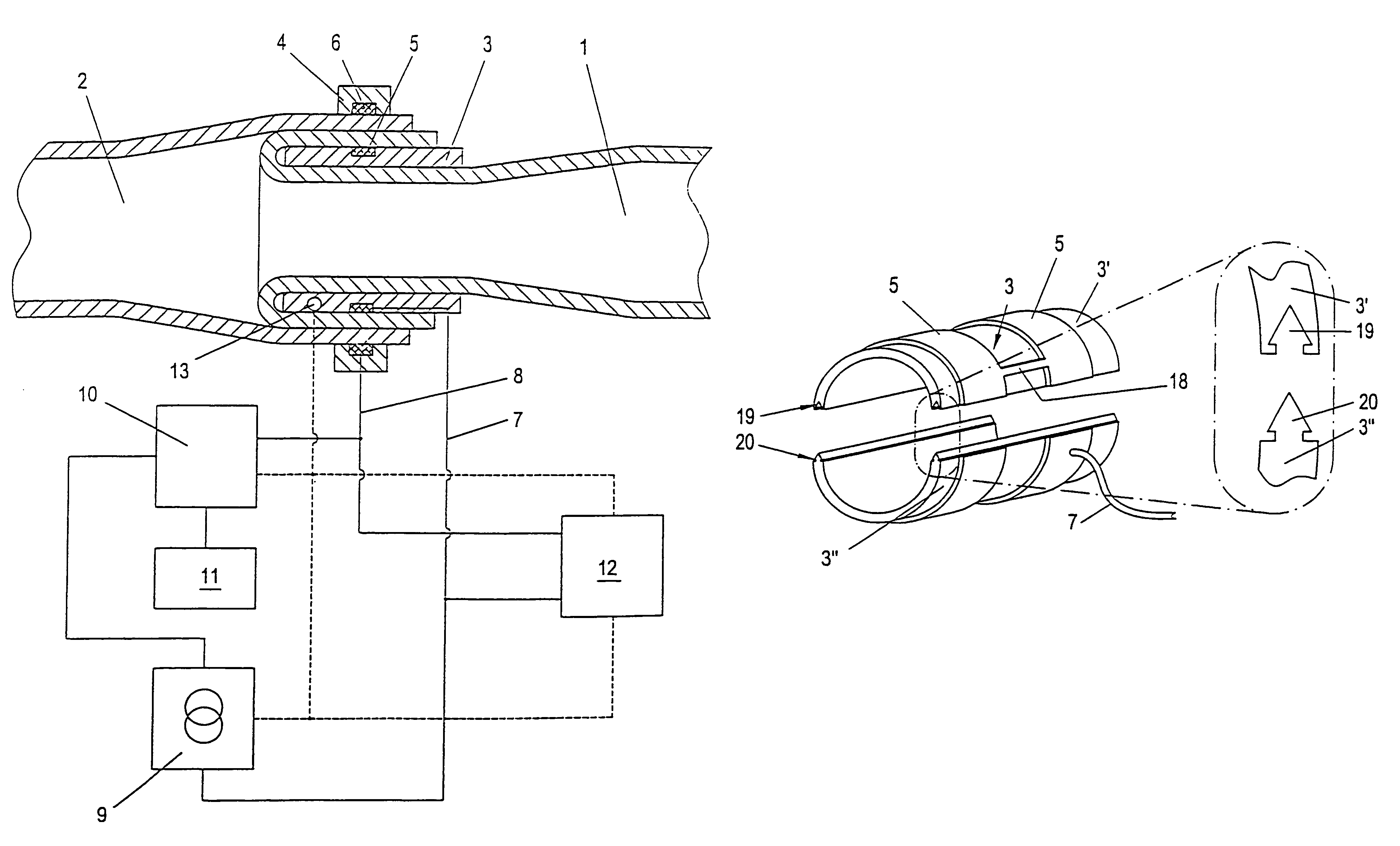
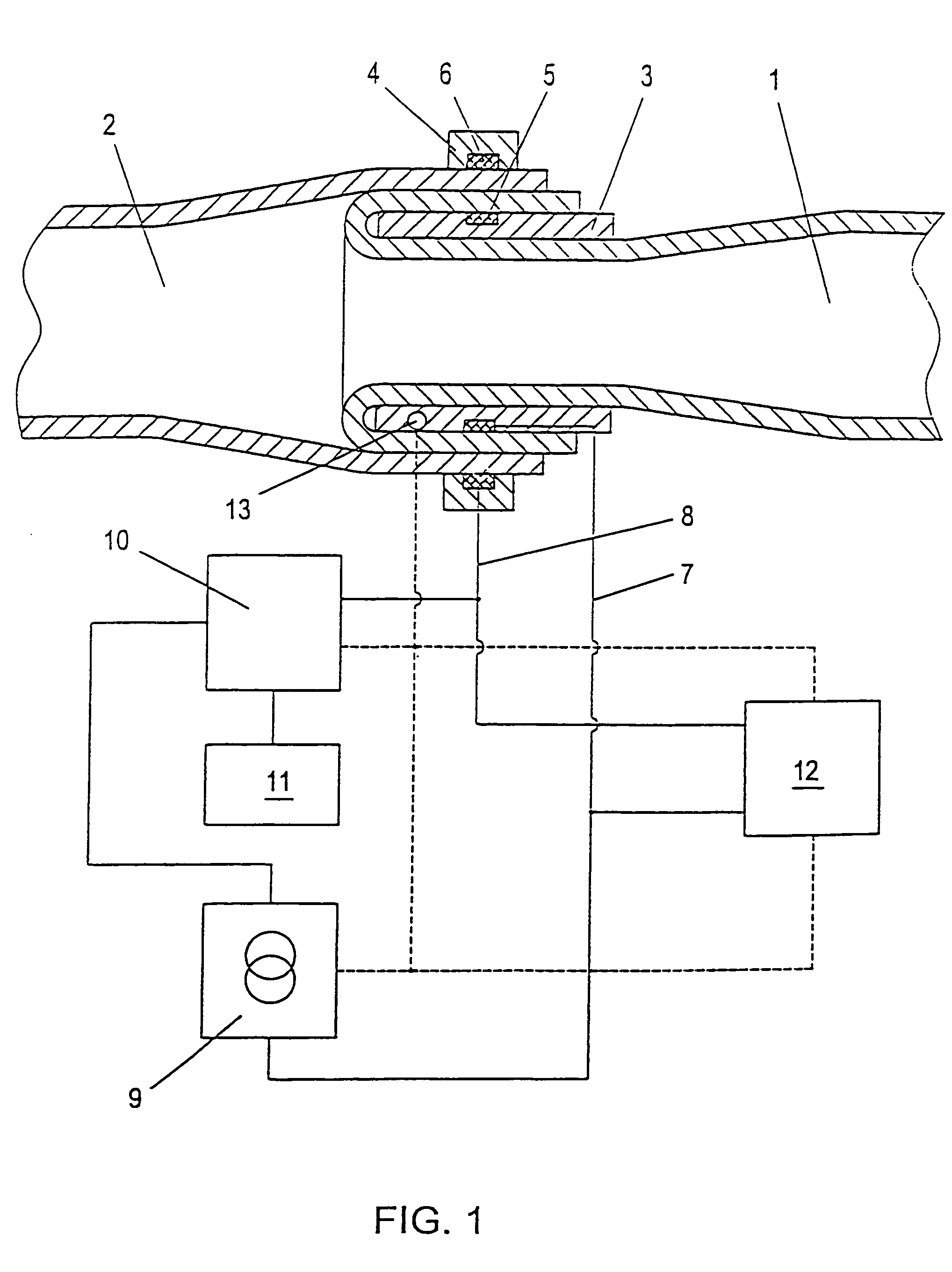
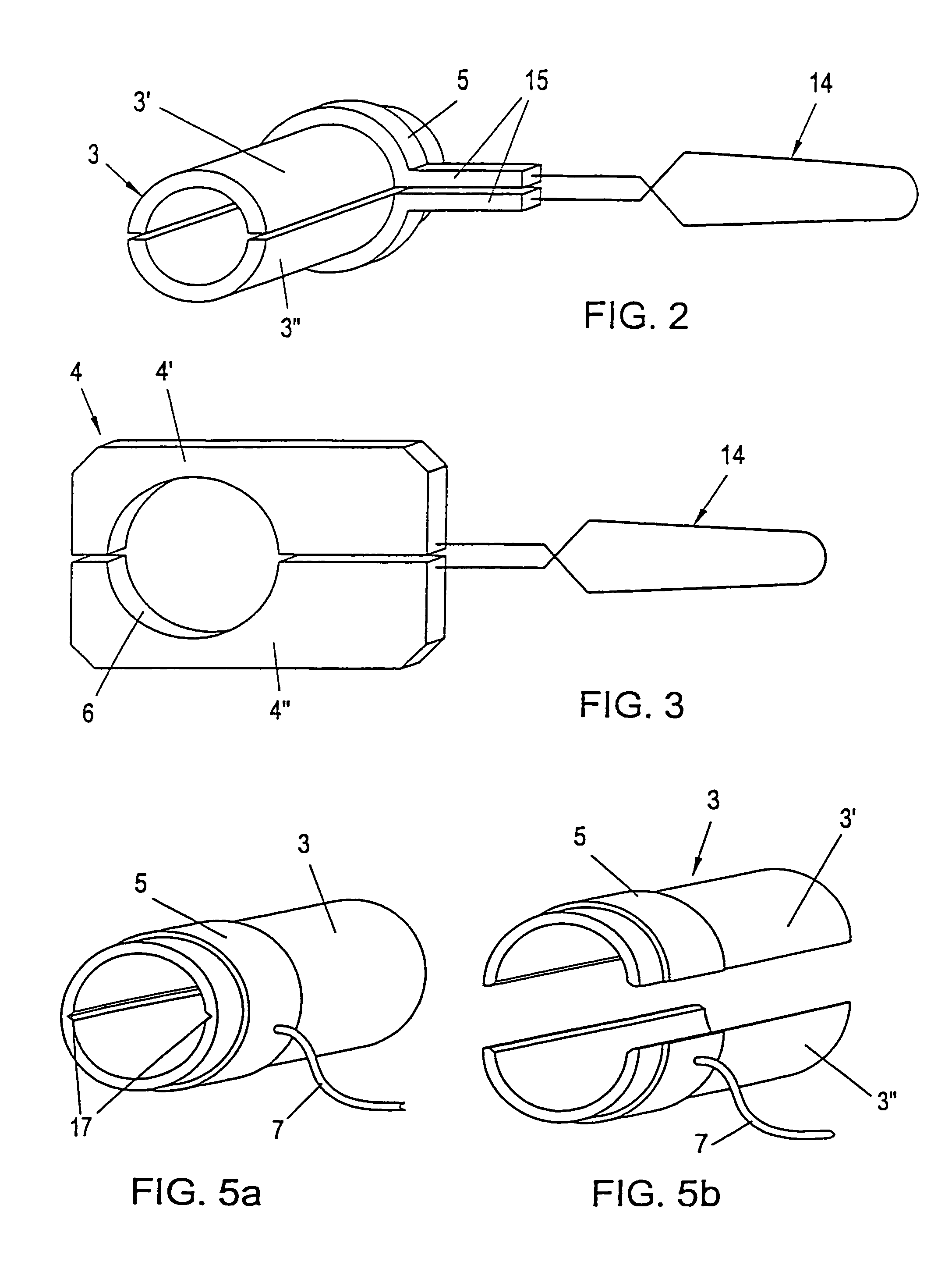
[0034]FIG. 1 shows a cross section through an end-to-end anastomosis of two hollow organs 1, 2, for example two arteries. Over the end of the hollow organ 1 a sleeve 3 has been pushed, and the end of the hollow organ 1 has been folded back over this sleeve 3. Then the end of the hollow organ 2 to be connected thereto is pushed over the inverted end of the first hollow organ 1, which now encloses the inner sleeve 3, and finally the outer sleeve 4 is placed over the inner sleeve 3. So that the sleeves 3, 4 can be removed after anastomosis is complete, each is designed to be separable. In accordance with the invention the inner sleeve 3 and the outer sleeve 4 both incorporate electrically conductive material, which preferably takes the form of corresponding contact surfaces 5, 6 in the sleeves 3, 4. It is likewise possible for the sleeves 3, 4 as a whole to be made of electrically conductive material. The contact surfaces 5, 6 are preferably disposed circumferentially around the sleeve...


PUM


Abstract

A device for producing anastomoses between hollow organs. The device includes an inner sleeve mounted around the end of the first hollow organ and an outer sleeve mounted around the end of the second hollow organ, the end being arranged over the end of the first hollow organ, which is turned inside out over the inner sleeve. The inner sleeve and outer sleeve are separable. In order to obtain a secure and durable anastomosis that is easy to carry out, the inner sleeve and outer sleeve comprise electricity-conducting materials, for example in the form of contact surfaces that can be connected to an external power or voltage to electrocoagulate the hollow organs that are to be joined.

Description

RELATED U.S. APPLICATIONS[0001]Not applicable.STATEMENT REGARDING FEDERALLY SPONSORED RESEARCH OR DEVELOPMENT[0002]Not applicable.REFERENCE TO MICROFICHE APPENDIX[0003]Not applicable.FIELD OF THE INVENTION[0004]The invention relates to a device for the production of anastomoses between hollow organs, with an inner sleeve to be mounted around the end of the first hollow organ and with an outer sleeve to be mounted around the end of the second hollow organ after the latter end has been arranged over the end of the first hollow organ, which has been turned inside out over the inner sleeve, the inner and outer sleeves being made separable so that they can be removed after anastomosis formation has been completed.BACKGROUND OF THE INVENTION[0005]The term “hollow organs” denotes, for example, blood vessels as well as the structures through which urine flows and the hollow organs of the digestive tract etc., and the need to connect such organs arises very often in surgery. In all such case...

Claims


Application Information

Patent Timeline
Patent Type & Authority Patents(United States)
IPC IPC(8): A61B17/11A61B18/04A61B18/14
CPCA61B17/11A61B18/1442A61B17/1114A61B2017/1107A61B2017/1132B60W2540/106B60W2720/106
Inventor SCHUBERT, HEINRICH
Owner ERBE ELEKTROMEDIZIN GMBH
Learn More