Wireless auxiliary monitoring and control system for an underwater installation

a control system and underwater installation technology, applied in the direction of transmission, electric devices, etc., can solve the problems of inability to monitor the lower stack, loss of data supply from sensors and valves in the stack, and inability to monitor the well operation conditions. , to achieve the effect of expanding the rang

Active Publication Date: 2012-11-06
CSIGNUM LTD
View PDF14 Cites 31 Cited by
  • Summary
  • Abstract
  • Description
  • Claims
  • Application Information

AI Technical Summary

Benefits of technology

[0016]A further object of the present invention is to provide an auxiliary system for local wireless control of an underwater installation which provides a soft shut-down mode for the underwater installation when disconnection of a hard wired control link via an umbilical and / or an associated riser is required.
[0017]A further object of the present invention is to provide an auxiliary system for local wireless control of an underwater installation which provides a safeguard against the effects of reconnection of a riser with an underwater installation when the state of the underwater installation is unknown.
[0018]A further object of the present invention is to provide an auxiliary system for local wireless control and monitoring of an underwater installation which is capable of operating for an extended time.

Problems solved by technology

Conditions requiring disconnection of the riser from the wellhead include bad weather, maintenance of the wellhead or other sections of the installation, and unstable operating conditions of the well.
When the marine riser is disconnected, there is no ability to control the lower stack; similarly, with the marine riser disconnected, the supply of data from the sensors and valves in the stack is lost so that there is no ability to monitor the lower stack.
Wireless monitoring and control of the lower stack would be preferable; however, prior art systems to not provide suitable means for wireless control and monitoring of a wellhead when the marine riser is disconnected.
Problems to be overcome with prior art wireless systems arise from the trade-off between the power required to drive the system for an extended time of operation and the quality of the underwater communications achievable.
The high rate of attenuation of electromagnetic signals underwater creates barriers against the use of electromagnetic signaling for wireless underwater control and monitoring for extended periods and over a long range.
However, systems based on the use of repeater stations require either wired electrical power for the repeater stations or provide operation for a limited duration using local batteries of the multiple repeaters.
Other systems such as optical systems and acoustic systems do not provide the required reliability: optical systems are affected by turbidity, and acoustic systems are affected by noise, reflections and other distortions when employed near fixed substantially metal installations.

Method used


Image

  • Wireless auxiliary monitoring and control system for an underwater installation
  • Wireless auxiliary monitoring and control system for an underwater installation
  • Wireless auxiliary monitoring and control system for an underwater installation

Examples


first embodiment

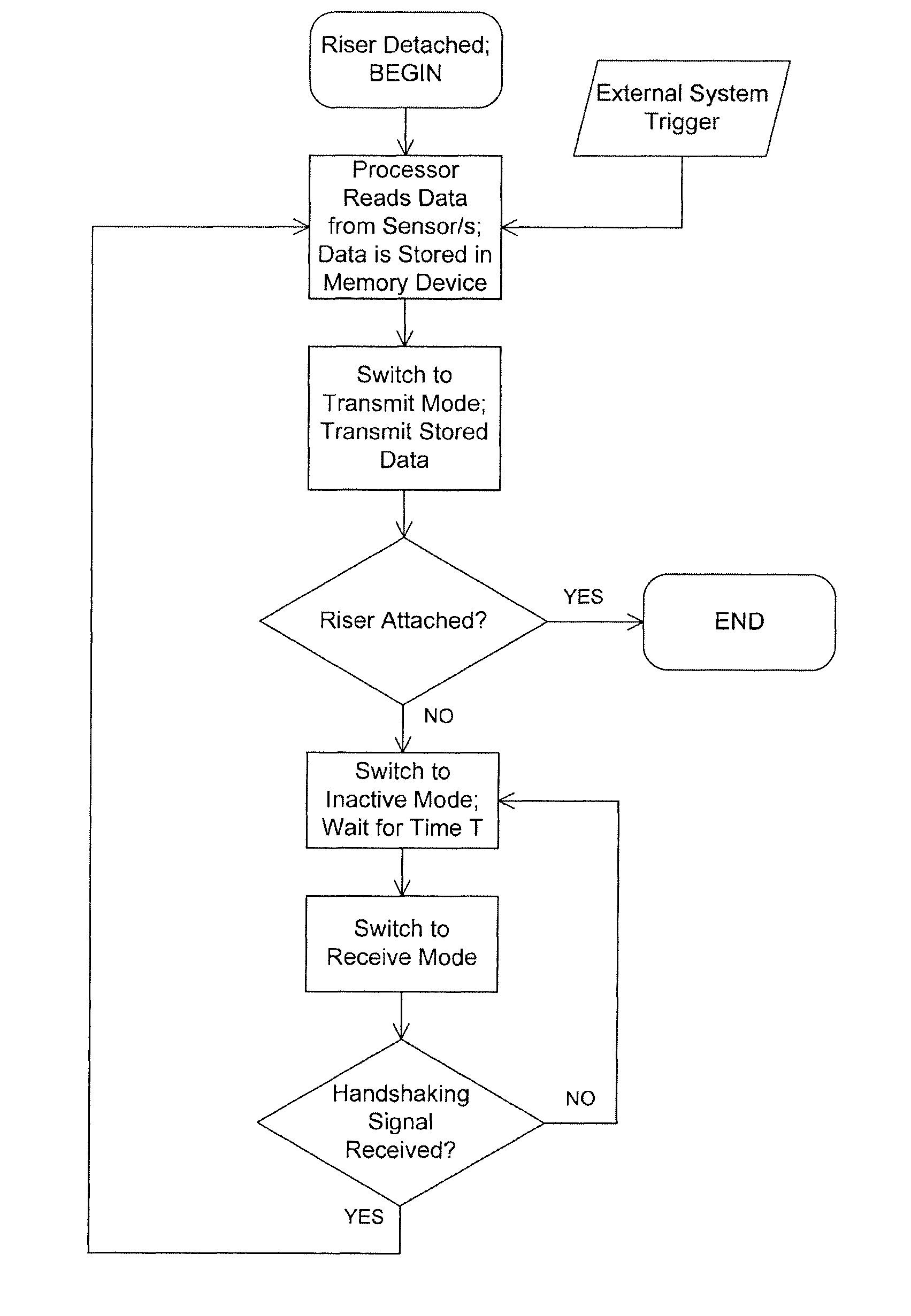
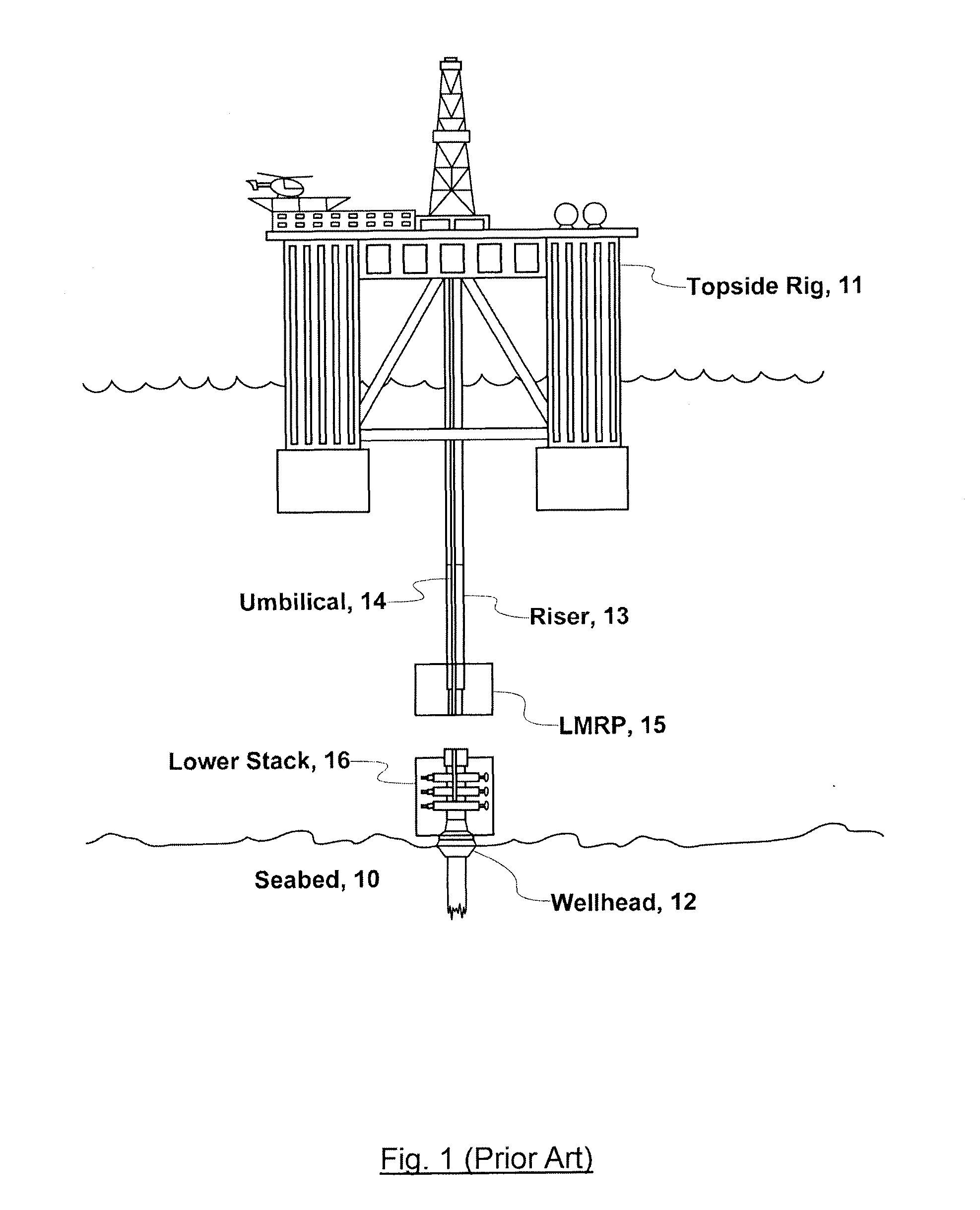
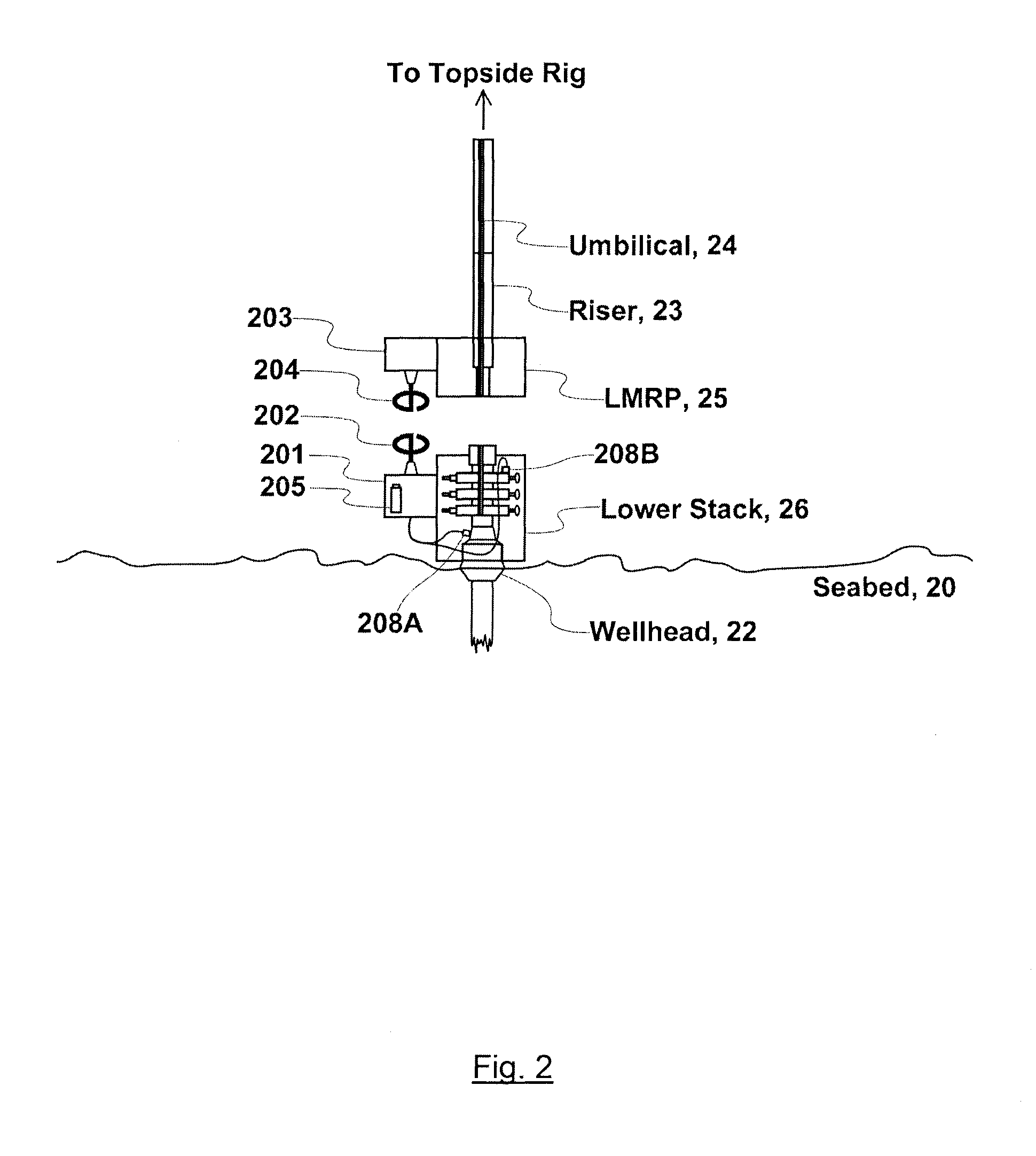
[0048]FIG. 2 shows a diagram of a wireless auxiliary monitoring system for an underwater installation according to the present invention. The underwater installation might form one section of a hydrocarbon drilling facility or a hydrocarbon production facility and comprises a lower stack 26, a lower marine riser package 25 and a well head 22 located on the seabed 20. A riser 23 connects to a topside rig or drilling vessel (not shown). During normal operation, the riser 23 is attached to the wellhead 22 via the lower marine riser package 25 and the lower stack 26. The lower stack 26 is fixed to the wellhead 22 on the seabed and comprises valves, pressure sensors and other devices (not shown) for maintaining and monitoring the state of the wellhead. An umbilical 24 associated with the riser 23 includes data and hydraulic lines for the monitoring and control of the wellhead; the control systems may be operated remotely from the topside rig (not shown). The lower marine riser package 25...

second embodiment

[0075]FIG. 5 shows a diagram of a wireless auxiliary control system for an underwater installation according to the present invention. The underwater installation might form one section of a hydrocarbon drilling or production facility and comprises a lower stack 56, a lower marine riser package 55 and a well head 52 located on the seabed 50. A riser 53 connects the wellhead 52 to a topside rig (not shown). During normal operation, the riser 53 is attached to the wellhead 52 via the lower marine riser package 55 and the lower stack 56. The lower stack 56 is fixed to the wellhead 52 on the seabed and comprises actuators, pressure sensors and other devices (not shown) for controlling the state of the wellhead. An umbilical 54 associated with the riser 53 includes data and hydraulic lines for the monitoring and control of the wellhead, the control systems may be operated remotely from the topside rig (not shown). Generally, umbilical 54 is affixed to the outside of the riser 53. The low...


PUM


Abstract

The present invention provides a wireless auxiliary system for monitoring and control of an underwater installation. The auxiliary system of the present invention sends data and control signals between an underwater installation—for example, a lower stack 26 in a hydrocarbon drilling or production facility—and an associated riser assembly 23. Data is collected by sensor network 208A, 208B and is transmitted from a first transceiver 201 to a second transceiver 203 by electromagnetic signals. First transceiver 201 is powered by a local power supply 205. To conserve power consumption, the first transceiver is designed to become active for a short time and then to switch to an inactive mode. For example, wireless data transfer may occur after the detachment or just prior to the reattachment of riser assembly 23 to the underwater installation. Wireless data transfer may also occur on receipt of a handshaking signal from second transceiver 203. Thus, the system of the present invention is capable of providing soft shut-down mode for the underwater installation on detachment of riser assembly 23 and can also safeguard potential risks of reattaching riser 23 when the underwater installation in an unknown state.

Description

CROSS-REFERENCE TO RELATED APPLICATION[0001]This application is a continuation in part of U.S. Ser. No. 11 / 454,630 now U.S. Pat. No. 7,711,322, which claims the benefit of U.S. Ser. Nos. 60 / 690,964, 60 / 690,966, and 60 / 690,959, all filed Jun. 15, 2005. All of the above applications are fully incorporated herein by reference.FIELD OF USE[0002]The present invention relates to the field of underwater exploration, hydrocarbon extraction facilities and plants, general underwater installations and other underwater and deep-sea applications.DESCRIPTION OF THE RELATED ART[0003]A typical hydrocarbon extraction facility comprises the following: a top side rig, which is located on the surface of the sea; a wellhead, where hydrocarbons are extracted from a well buried in the seabed; a production riser which connects from the wellhead on the seabed to the topside rig and which acts as a conduit for fluids between the rig and the wellhead; an umbilical which runs along the riser and which provides...

Claims


Application Information

Patent Timeline
Patent Type & Authority Patents(United States)
IPC IPC(8): H04B13/02
CPCH04B13/02
Inventor JAFFREY, ANDREWHYLAND, BRENDAN
Owner CSIGNUM LTD
Why Eureka
Try Eureka