System and method for multi-camera visual odometry

a multi-camera, visual odometry technology, applied in the field of video image processing, can solve the problems of inability to accurately determine the location of objects

Active Publication Date: 2012-11-06
SRI INTERNATIONAL
View PDF2 Cites 20 Cited by
  • Summary
  • Abstract
  • Description
  • Claims
  • Application Information

AI Technical Summary

Benefits of technology

[0012]It is an object of the present invention to provide a means for exploiting features across a wide swath of an imaged scene in order to create an exceptionally high degree of robustness to the presence of independent foreground object motion and lack of quality trackable features in any particular portion of the imaged scene.
[0013]It is another object of the present invention to provide a means for landmark matching of features across multiple cameras and over time in order to create an exceptionally high degree of robustness to dropped frames, as well as other system or capture failures, that may occur during critical maneuvers that are known to break a tracking process.
[0014]It is yet another object of the present invention to provide improved precision in the tracking of points across multiple cameras over a wide field of view, which in turn provides for sufficiently strong constraints in the estimation of three-dimensional motions of the video sensor.

Problems solved by technology

However, there are inherent uncertainties in discerning relative movement from various sensors.
For example, if there is a slight inaccuracy in the measured distance and direction traveled during an iteration of the mapping sequence, then errors will be traversed to subsequent features added to the map.
When these positional errors go unchecked or undetected, the map becomes grossly distorted and, therefore, the ability to precisely determine location becomes significantly compromised.
Yet, successfully developing a robust SLAM structure from motion systems, which can be configured to function over significantly longer periods of time using video data from passive two-dimensional cameras, continues to remain a challenge.
Although these developments are impressive and continue to contribute to improved methods for implementing visual odometry, they are still deficient in that they lack the robustness necessary for autonomous applications over extended periods of time.
Various factors can contribute to and result in the break down of algorithms, such as, the familiar problematic dropping of video frames during turning maneuvers, presence of artifacts during video capture, video frames comprised of minimal image features or no image features at all, significant foreground object motion obscuring an imaged scene and / or considerable sensor motion preventing reliable tracking of image features.

Method used


Image

  • System and method for multi-camera visual odometry
  • System and method for multi-camera visual odometry
  • System and method for multi-camera visual odometry

Examples


Embodiment Construction

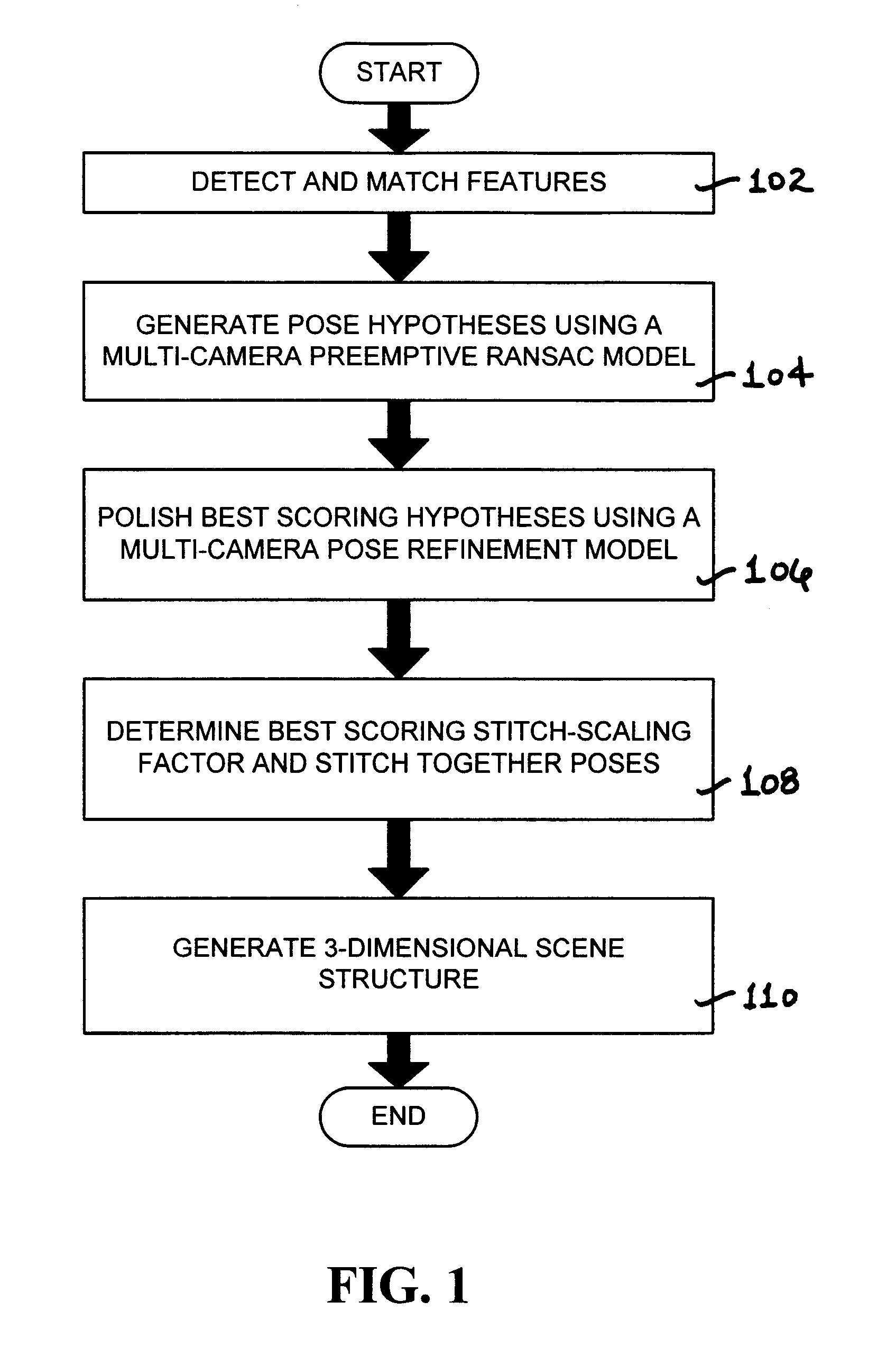
[0023]The present invention is directed to improved visual odometry methods for a distributed aperture system. For purposes of clarity, and not by way of limitation, illustrative views of the present invention are described with references made to the above-identified figures. Various modifications obvious to one skilled in the art are deemed to be within the spirit and scope of the present invention.

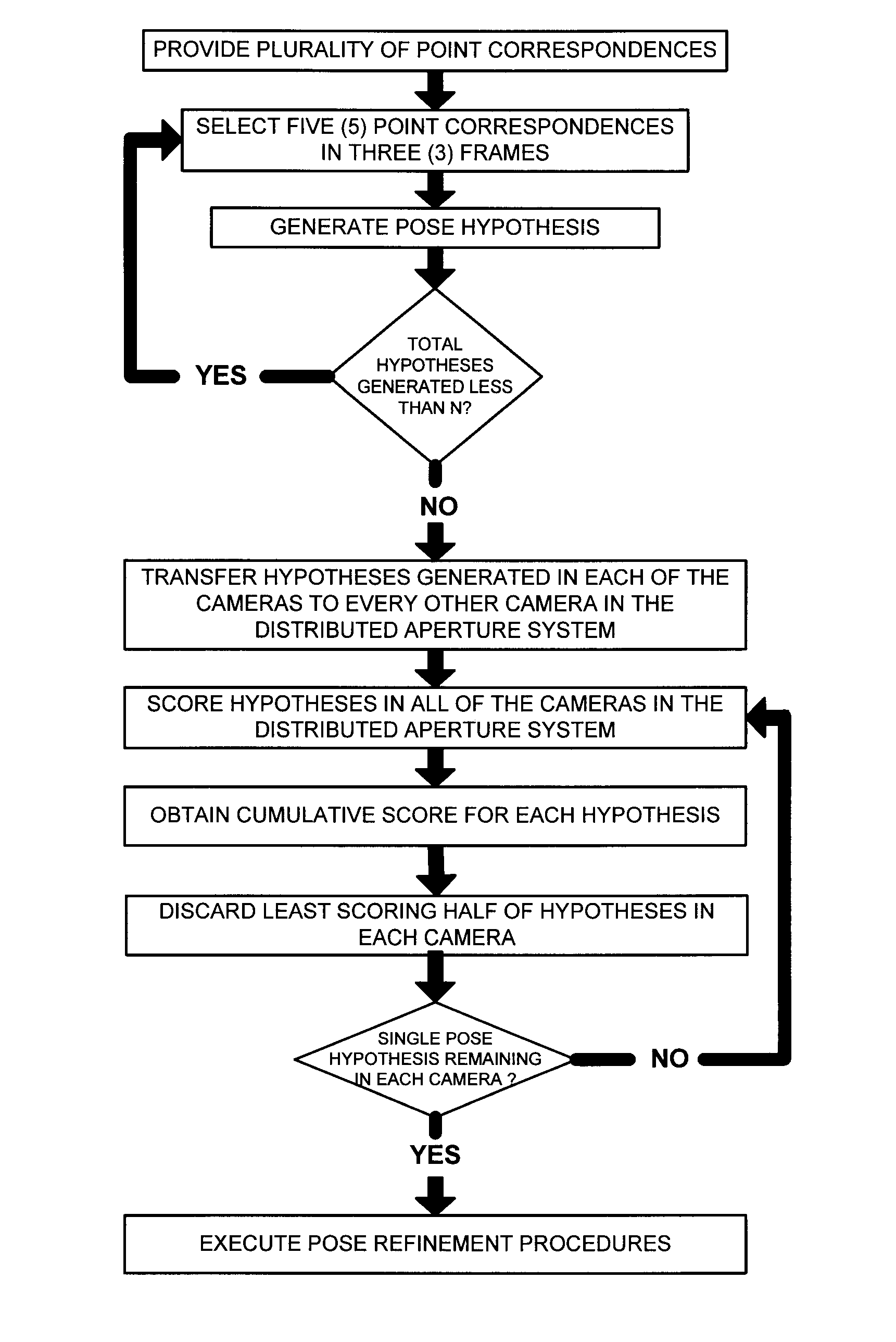
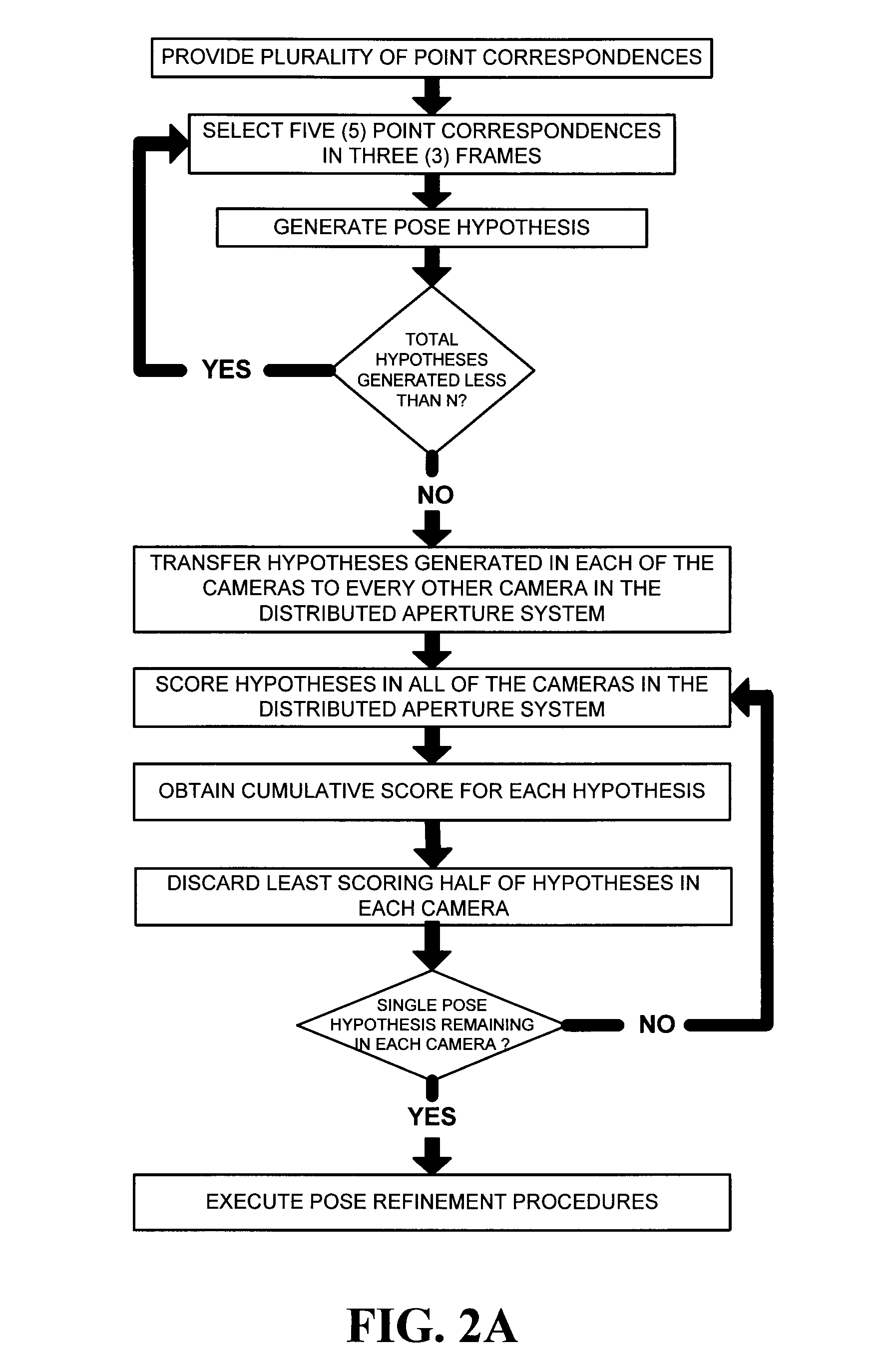
[0024]In a distributed aperture system employing multiple cameras, visual odometry is typically applied in each of the cameras individually for purposes of estimating the pose of each of the cameras. However, due to the relative poses of each of the cameras being of a fixed and known configuration, single-camera results are constrained. In order to take advantage of these constraints, it is necessary to provide a method for computing the poses of all the cameras in a distributed aperture system given the pose of any one camera. The present invention takes advantage of these constraints ...


PUM


Abstract

A visual odometry system and method for a fixed or known calibration of an arbitrary number of cameras in monocular configuration is provided. Images collected from each of the cameras in this distributed aperture system have negligible or absolutely no overlap. The relative pose and configuration of the cameras with respect to each other are assumed to be known and provide a means for determining the three-dimensional poses of all the cameras constrained in any given single camera pose. The cameras may be arranged in different configurations for different applications and are made suitable for mounting on a vehicle or person undergoing general motion. A complete parallel architecture is provided in conjunction with the implementation of the visual odometry method, so that real-time processing can be achieved on a multi-CPU system.

Description

CROSS-REFERENCE TO RELATED APPLICATIONS[0001]This application claims the benefit of U.S. Provisional Patent Application No. 60 / 717,722, filed Sep. 16, 2005, which is incorporated by reference herein in its entirety.STATEMENT REGARDING FEDERALLY SPONSORED RESEARCH OR DEVELOPMENT[0002]The U.S. Government has a paid-up license in this invention and the right in limited circumstances to require the patent owner to license others on reasonable terms as provided for by the terms of Contract No. DAAB07-01-9-L504 awarded by DARPA.BACKGROUND OF THE INVENTION[0003]1. Field of the Invention[0004]The present invention relates to the field of video image processing. More particularly, the present invention is directed to visual odometry methods for a distributed aperture system.[0005]2. Description of the Prior Art[0006]An important aspect of today's computer vision systems is in the recovery and processing of three-dimensional pose (i.e., position and orientation) information associated with mo...

Claims


Application Information

Patent Timeline
Patent Type & Authority Patents(United States)
IPC IPC(8): H04N13/00
CPCH04N5/232H04N23/64
Inventor OSKIPER, TARAGAYFIELDS, JOHNKUMAR, RAKESH
Owner SRI INTERNATIONAL
Why Eureka
Try Eureka