Spectroscopic imaging method and system for exploring the surface of a sample

a raman microscope and imaging method technology, applied in the field of raman microscopes, can solve the problems of too important time required to obtain raman images with classical raman microscopes, slow data transfer process to the central unit, etc., and achieve the effect of reducing the time required

Active Publication Date: 2012-11-13
HORIBA JOBIN YVON
View PDF12 Cites 4 Cited by
  • Summary
  • Abstract
  • Description
  • Claims
  • Application Information

AI Technical Summary

Benefits of technology

[0009]One aim of the present invention consists to provide a spectroscopic imaging system for exploring the surface of a sample enabling to reduce times required to obtain a two-dimensional map of a sample surface.
[0010]Time required for scanning the sample surface and time required for transferring the data from the CCD detector to the imaging device are significantly reduced.
[0012]Another aim of the present invention consists to provide a spectroscopic imaging method enabling to localize rapidly one or several elements having spectroscopic property at the sample surface, even if the size of the element is in the order of the micrometer.
[0034]The present invention permits reducing the times required for data transfer between the detection means and the imaging device as well as increasing the data rate. The data rate is the speed of a data transfer process, normally expressed in Hz.
[0062]The association of the scanning means with the storage means of the detection means enables to obtain a spectral image such as a Raman image in less than 10 minutes, with a good precision (50 points×50 points). Time required to obtain a spectral image is significantly reduced. The using of scanning means such as galvanometric mirrors permits to reduce the time t required to scan the sample surface. And the using of storage means such as FPGA permits to reduce the time required for transferring the data from the detector to the FPGA and the time required for transferring the data from the FPGA to the imaging device.

Problems solved by technology

Nevertheless, with classical CCD detectors, the process for transferring the data from the CCD detector to the central unit is slow.
Times required to obtain a Raman image with classical Raman microscope are too important.

Method used


Image

  • Spectroscopic imaging method and system for exploring the surface of a sample
  • Spectroscopic imaging method and system for exploring the surface of a sample
  • Spectroscopic imaging method and system for exploring the surface of a sample

Examples


Embodiment Construction

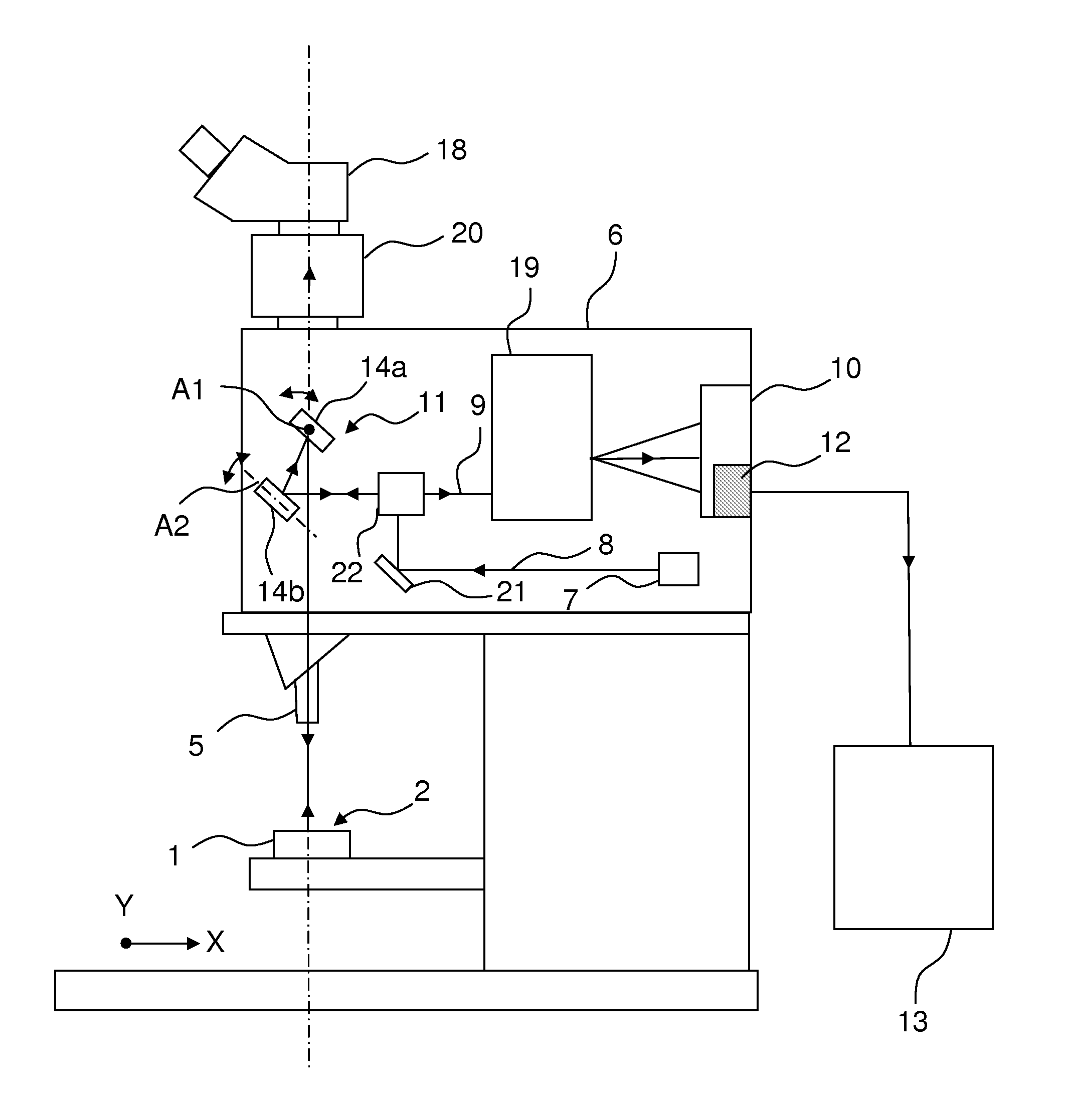
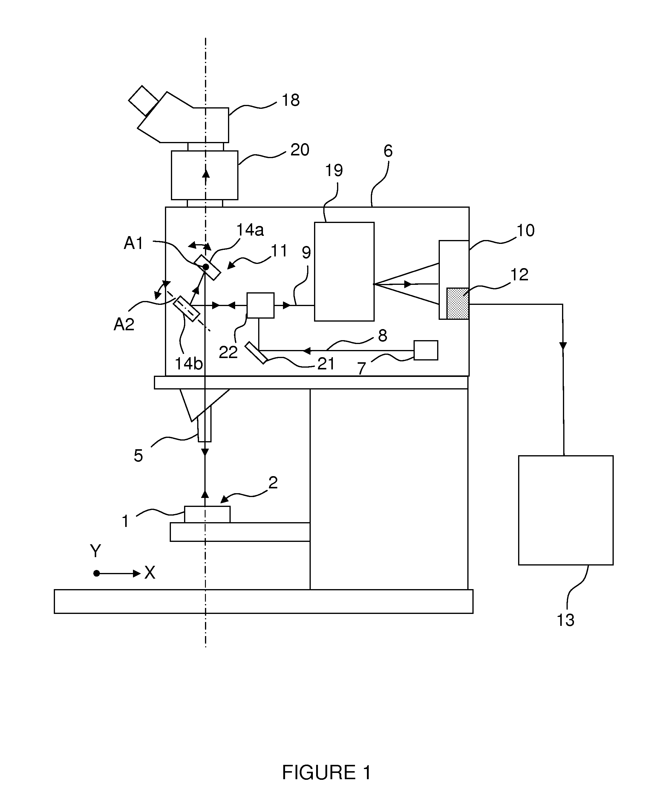
[0069]FIG. 1 is a schematic representation of a spectroscopic imaging system for exploring the surface 2 of a sample 1, according to one embodiment of the invention.

[0070]The spectroscopic imaging system comprises a microscopic or macroscopic device which can be an infinity corrected microscope, as described in the document U.S. Pat. No. 7,102,746.

[0071]In infinity corrected microscopes, visible light gathered from a sample 1, is collimated by an objective 5 which can be a lens, and is formed into an image by a tube lens (not shown), usually located within a viewing device 18. Because light is collimated between the objective 5 and the tube lens, many components may be inserted in this region without substantially affecting imaging quality.

[0072]The spectroscopic imaging system comprises a housing 6 including a spectroscope. The housing 6 of the spectroscopic imaging system can be definitely fixed to the microscopic or macroscopic device in a not movable manner. Alternatively, the s...


PUM


Abstract

A spectroscopic imaging system includes a microscopic or macroscopic device including an objective, a housing including a spectroscope, and scanning means disposed between the objective and the spectroscope. During the scanning of the excitation beam on a scanned area on the sample surface, the energy of the emitted light beam is integrated on the pixels of the detection means, generating average spectral data for each line of pixels. Storage means are connected to the detection means, including a memory able to store average spectral data of M lines of pixels. An imaging device is connected to the storage means, and the average spectral data of M lines of pixels are sent simultaneously toward the imaging device in order to obtain an average spectroscopic image of the scanned area.

Description

BACKGROUND OF THE INVENTION[0001]The invention concerns a spectroscopic imaging method and system for exploring the surface of a sample.[0002]It is particularly useful in Raman spectroscopy. It can equally be used in other forms of spectroscopy such as photoluminescence, fluorescence or cathodoluminescence.[0003]Raman spectroscopy is an analytical technique providing molecule-specific information about a sample. When monochromatic light or radiation strikes a sample, the sample interacts with the light. A portion of the incident radiation may be scattered by the sample. Scattered radiation may contain both an elastic component, in which radiation frequencies remain unchanged, and inelastic components with altered frequencies. Elastically scattered components are called Rayleigh scattering. Inelastic components, if caused by light interacting with the vibrations of molecular bonds, are called Raman scattering.[0004]A prior Raman analysis apparatus is described in a paper “Raman Micro...

Claims


Application Information

Patent Timeline
Patent Type & Authority Patents(United States)
IPC IPC(8): G01J3/44
CPCG01J3/2803G01J3/2823G01J3/44G01N21/65G01N2021/656
Inventor ROUSSEL, BERNARDRAPAPORT, ALEXANDRAKOKOTA, ALEXANDRE
Owner HORIBA JOBIN YVON
Why Eureka
Try Eureka