Cochlear lead

a cochlea and electrode array technology, applied in the direction of head electrodes, internal electrodes, therapy, etc., can solve the problems of conductive hearing loss, impeded normal mechanical pathways for sound to reach the hair cells in the cochlea, and deafness sensorineural hearing loss

Active Publication Date: 2012-11-13
ADVNACED BIONICS LLC
View PDF35 Cites 7 Cited by
  • Summary
  • Abstract
  • Description
  • Claims
  • Application Information

AI Technical Summary

Benefits of technology

[0018]In another embodiment of the cochlear lead, the distal portion of the electrode array may have cross-sectional areas that are substantially or significantly smaller than the corresponding spaces of the selected cochlear duct, which duct is preferably the scala tympani. This facilitates the distal portion of the electrode array to assume a position closer to the lateral wall of the cochlea (lateral position) within the selected cochlear duct, e.g., the scala tympani.

Problems solved by technology

Of these, conductive hearing loss occurs where the normal mechanical pathways for sound to reach the hair cells in the cochlea are impeded, for example, from damage to the ossicles.
In many people who are profoundly deaf, however, the reason for their deafness is sensorineural hearing loss.
Individuals with sensorineural hearing loss are unable to derive any benefit from conventional hearing aid systems no matter how loud the acoustic stimulus is, because the mechanism for transducing sound energy into auditory nerve impulses has been damaged.
Thus, in the absence of properly functioning hair cells, auditory nerve impulses cannot be generated directly from sounds.
In practice, however, this goal can be difficult to realize because of the particular anatomy of the cochlea.
While the electrode array with a spiral-shaped carrier shown in the '647 patent represents a significant advance in the art, it lacks sufficient shape memory to allow it to return to its original curvature (once having been straightened for initial insertion) and to provide sufficient hugging force to wrap snugly against the modiolus of the cochlea.
While the electrode arrays taught in the above-referenced '219 and '585 patents are based on the correct goal, i.e., to force the electrode carrier into a close hugging engagement with the modiolus, it does so by using an additional element that makes lead manufacture more difficult and expensive.

Method used


Image

  • Cochlear lead
  • Cochlear lead
  • Cochlear lead

Examples


Embodiment Construction

[0023]The following description is of the best mode presently contemplated for carrying out the invention. This description is not to be taken in a limiting sense, but is made merely for the purpose of describing the general principles of the invention. The scope of the invention should be determined with reference to the claims.

[0024]The cochlear lead of the present invention may be used with an implantable multi-channel pulse generator, e.g., an implantable cochlear stimulator (ICS) of the type disclosed in U.S. Pat. No. 5,603,726, incorporated herein by reference in its entirety or with other suitable stimulators.

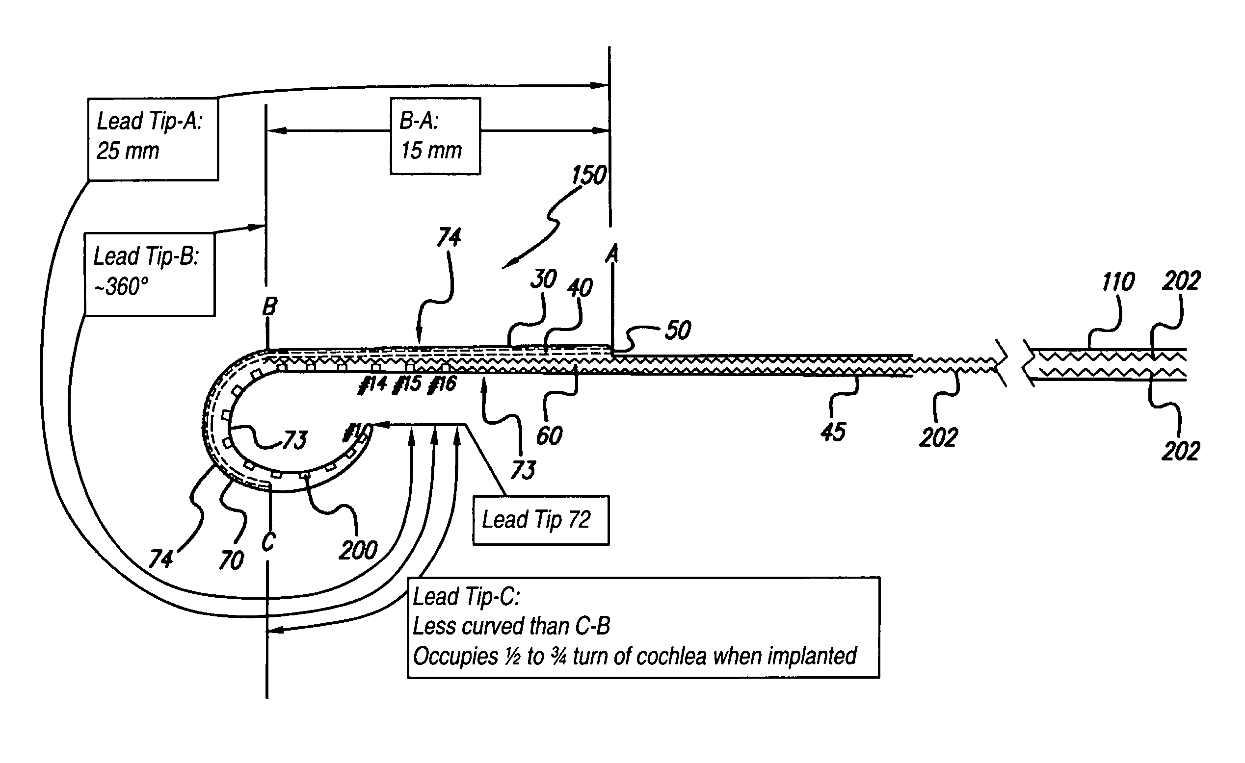
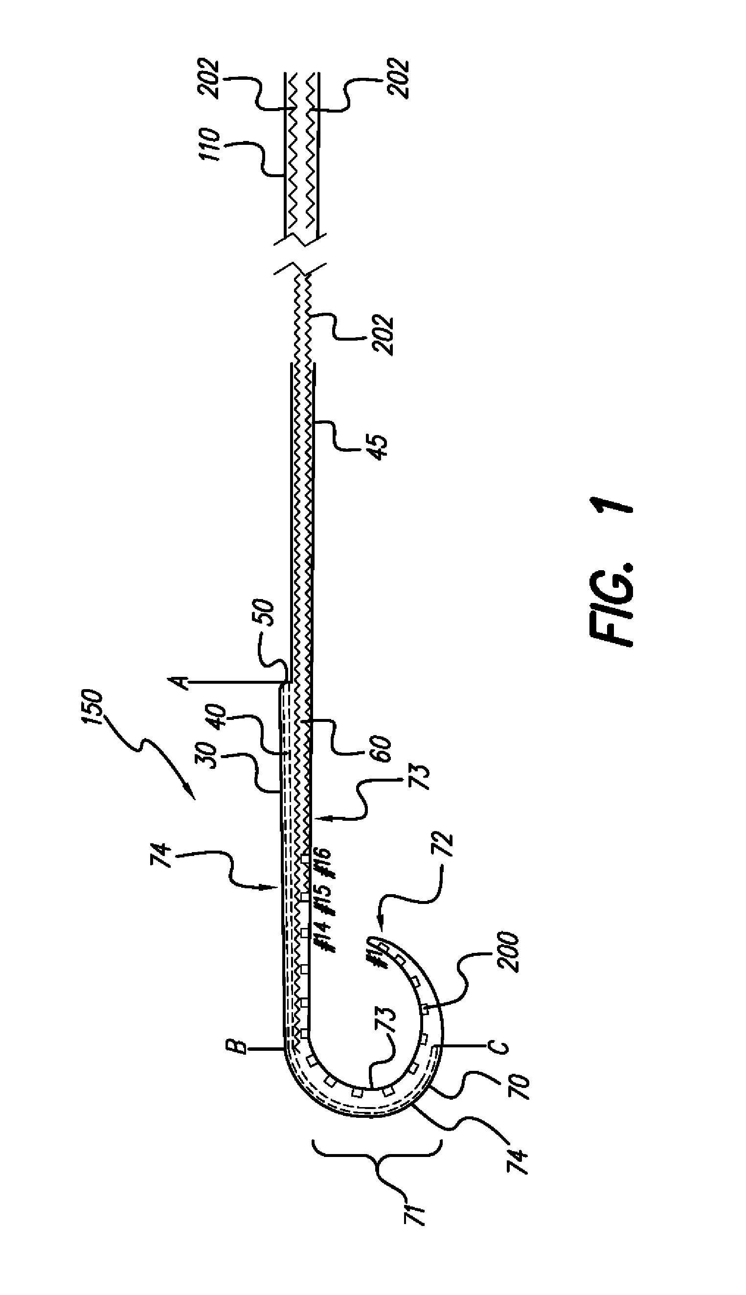
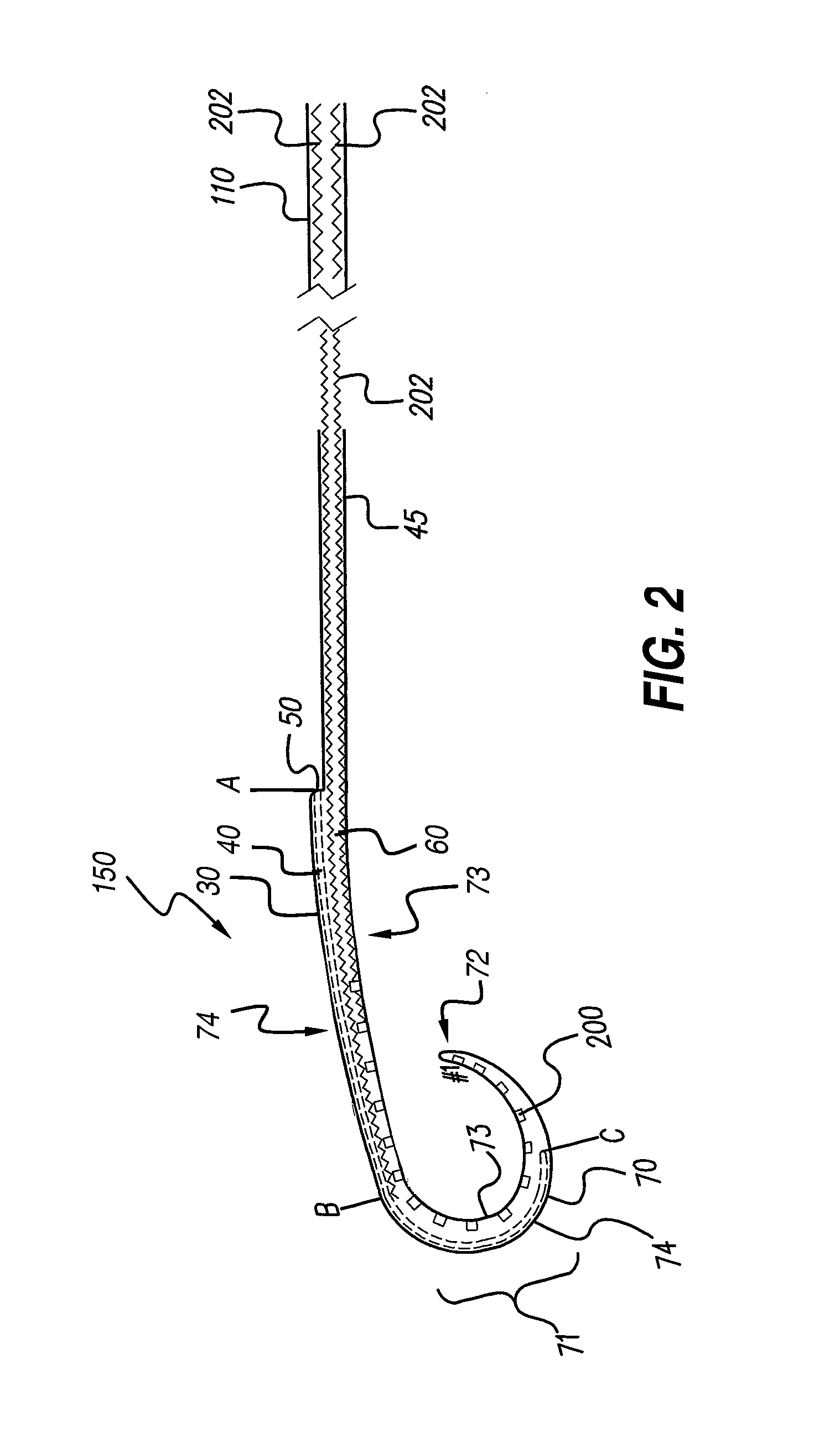
[0025]FIG. 1 shows an embodiment of the lead 150, in accordance with the present invention. The electrode contacts 200 are spaced apart along the medial side of the lead, which side is on the inside of the curvature of the curved electrode array. In the lead embodiment shown, the electrode contacts in the electrode array are positioned “in-line” to the lead, meaning that...


PUM


Abstract

An electrode array design is provided which is intended for deep insertion into a human cochlea. The distal most portion of the lead can be very thin and flexible and have a wider arc than the remainder of the curved electrode array portion of the lead, which has a more aggressive arc. As a result, the distal most portion of the electrode array can be laterally positioned in a selected cochlear duct, whereas, concurrently, the remaining, more proximal part of the electrode array may be positioned medially (perimodiolar) within the cochlear duct.

Description

[0001]The present application claims the benefit of U.S. Provisional Patent Application Ser. No. 60 / 574,473, filed 26 May 2004, which application is herein incorporated by reference in its entirety.BACKGROUND OF THE INVENTION[0002]The present invention relates to implantable stimulation devices, and, more particularly, to electrode arrays for stimulation of the cochlea. Electrode arrays consist of electrode contacts generally placed along one side of an elongate carrier so that when the array is implanted within one of the cochlear ducts such as the scala tympani, the electrode contacts are positioned in close proximity to the cells that are to be stimulated, allowing such cells to be stimulated with minimal power consumption.[0003]For purposes of clarity, as used herein, an implantable stimulating lead is a device that has one or more electrode contacts that deliver current to tissue to be stimulated. An electrode contact is that part of the stimulating device which is actually ele...

Claims


Application Information

Patent Timeline
Patent Type & Authority Patents(United States)
IPC IPC(8): A61N1/04A61N1/05
CPCA61N1/0541
Inventor FRIJNS, JOHANNES H. M.KUZMA, JANUSZ A.BRIAIRE, JEROEN JOHANNES
Owner ADVNACED BIONICS LLC
Why Eureka
Try Eureka