Weather strip structure

a weather strip and structure technology, applied in the field of weather strip structure, can solve the problems of limiting the ability to increase the degree of sealing and achieve the effect of preventing water from entering the inside, increasing the sealing pressure against the window glass, and increasing the degree of sealing the water entry channel between the weather strip and the window glass

Active Publication Date: 2012-11-20
TOYOTA JIDOSHA KK
View PDF84 Cites 6 Cited by
  • Summary
  • Abstract
  • Description
  • Claims
  • Application Information

AI Technical Summary

Benefits of technology

[0008]According to the feature or example embodiment described above, the bottom wall, the outer wall and the inner wall produce a substantially C-shaped cross section, and the weather strip seals the channel around the window glass (along the surface thereof), by sandwiching the peripheral portion of the window glass between the outer wall and the inner wall. In this sealed state, a gap (space) is created by the side groove between the window glass and the at least one of the outer wall or the inner wall. Thus, with the present weather strip structure, entrance of water into the interface between the window glass and the outer wall or the inner wall due to capillarity, for example, is effectively prevented. In other words, it is possible to effectively prevent water from entering the inside of the vehicle through the interface between the weather strip and the window glass.
[0010]According to the second feature or example embodiment described above, the bottom wall, the outer wall and the inner wall produce a substantially C-shaped cross section, and the weather strip seals the channel around the window glass (along the surface thereof), by sandwiching the peripheral portion of the window glass between the outer wall and the inner wall. In this sealed state, the lip protruding from one or each of the outer wall and the inner wall is in pressure contact (elastic contact) with the window glass. Thus, with the present weather strip structure, higher sealing pressure against the window glass is achieved, and the degree of sealing the water entrance channel between the weather strip and the window glass is increased. In particular, because the lip disposed between the bottom wall and the free end of the outer wall or the inner wall is not exposed on the open end side of the weather strip structure, the sealing portion is protected, and the lip can exhibit the required degree of sealing. Thus, it is possible to effectively prevent water from entering into the inside of the vehicle through the interface between the weather strip and the window glass.
[0011]With the above features, because a seal is provided at a location spaced from the open end of the weather strip, this seal can avoid the high pressures to which the open end (at the free ends of the inner and outer walls) might be exposed, and thus sealing is improved. However, under certain conditions, water could nevertheless pass through the improved seal arrangement. Thus, as an alternative to the above improved seal features, or more preferably in addition to one or more of the improved seal features, the present invention also provides improved arrangements for handling water that could pass between the window glass and one of the walls of the weather strip structure. Such additional or alternate features can include, for example, a drainage through hole and / or a drainage groove as discussed herein.
[0013]According to the third feature or example described above, the bottom wall, the outer wall and the inner wall produce a substantially C-shaped cross section, and the weather strip seals the channel at a lower portion of the window glass (along the surface thereof), by sandwiching a lower edge portion of the window glass between the outer wall and the inner wall. The water that enters through the interface between the outer wall and the window glass is drained out through the through hole in the bottom wall. In a preferred example of the present weather strip structure, the through hole is offset toward the outside of the vehicle body with respect to the lower end face of the window glass, which prevents the end face of the window glass from closing the through hole. Thus, with the present weather strip structure, required drainage capacity provided by the through hole is ensured. Accordingly, it is possible to effectively prevent water from entering the inside of the vehicle through the interface between the weather strip and the window glass.
[0015]According to the fourth feature or example described above, the bottom wall, the outer wall and the inner wall produce a substantially C-shaped cross section, and the weather strip seals the channel at a lower portion of the window glass (along the surface thereof), by sandwiching a lower edge portion of the window glass between the outer wall and the inner wall. The water that enters through the interface between the outer wall and the window glass is led to the through hole via the bottom groove and is drained out through the through hole. In the present weather strip structure, the bottom wall (the part thereof between the inner and outer walls) that has substantially the same width as that of the window glass is provided with the bottom groove (for example in the form of a concave portion), which prevents the lower end portion of the window glass from occupying the bottom groove. Thus, with the present weather strip structure, required drainage capacity provided by the bottom groove and the through hole is ensured. Accordingly, it is possible to effectively prevent water from entering the inside of the vehicle through the interface between the weather strip and the window glass.
[0017]As described above, with the weather strip structure according to the invention, it is possible to effectively prevent water from entering the inside of the vehicle through the interface between the weather strip and the window glass.

Problems solved by technology

However, in the arrangement described above, the degree of sealing is increased by merely increasing the contact pressure against the window glass on the open end side, which can limit the ability to increase the degree of sealing between the weather strip and the window glass.

Method used


Image

  • Weather strip structure
  • Weather strip structure
  • Weather strip structure

Examples


Embodiment Construction

[0026]Referring now to the drawings, like reference numerals are utilized to designate identical or corresponding parts throughout the several views.

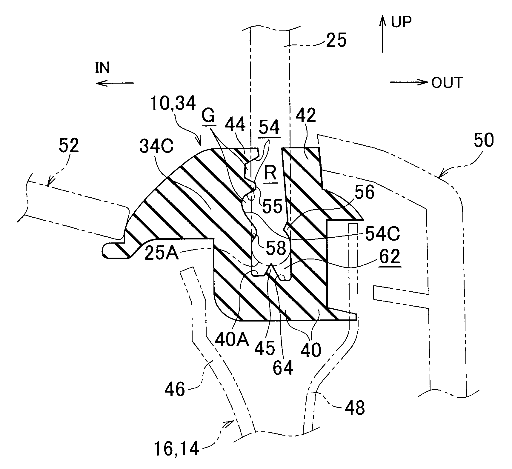
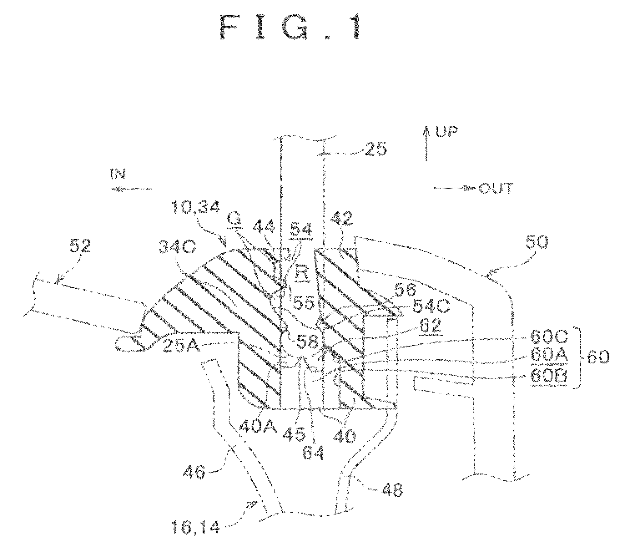
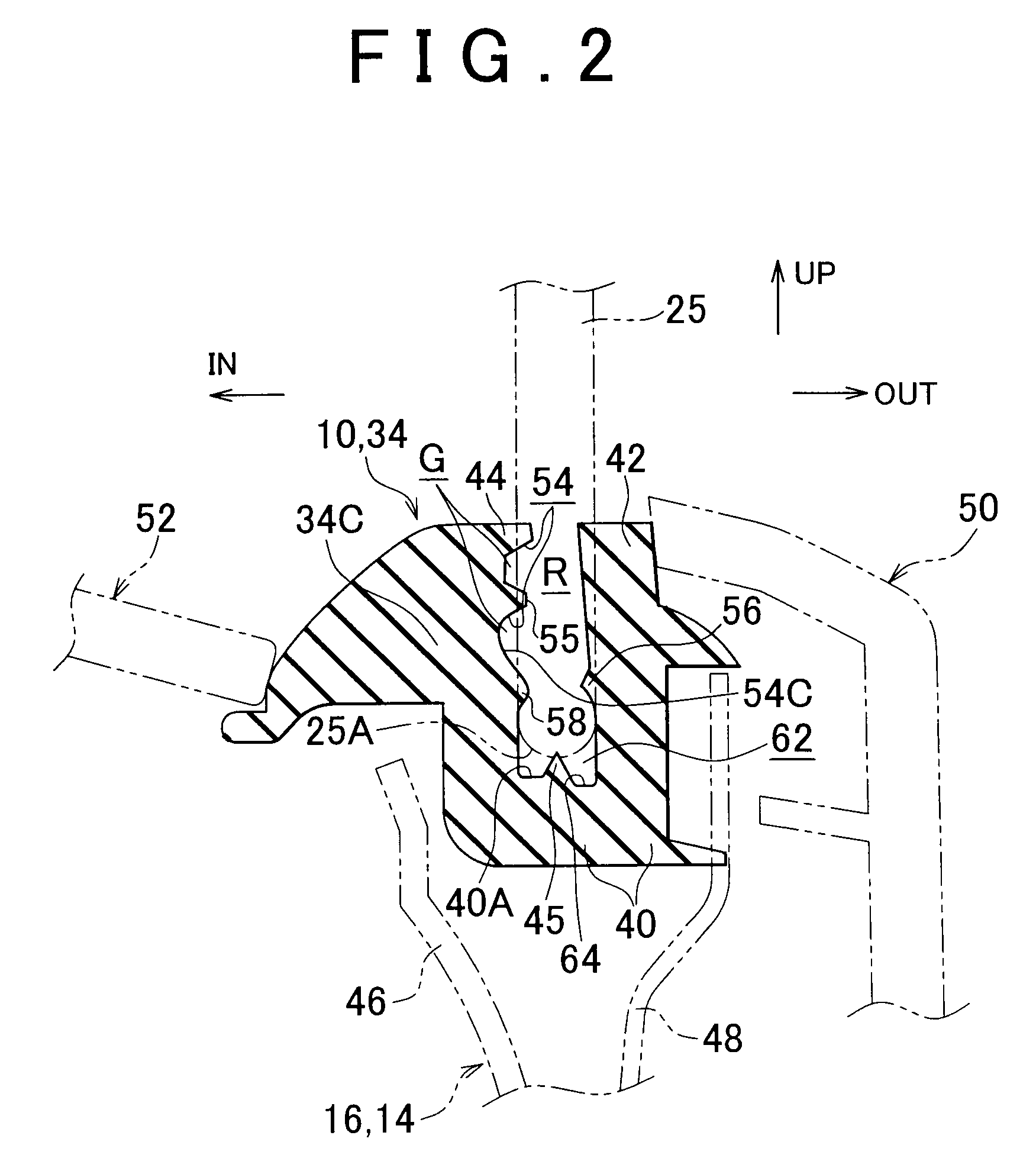
[0027]A weather strip 10 which includes a weather strip structure according to an example of an embodiment of the invention will be described with reference to FIGS. 1 to 5. The arrow FR (FIGS. 3 and 5) drawn in the figures as appropriate indicates the forward direction of the longitudinal (travel) directions with respect to a vehicle body of an automobile A. The arrow UP indicates the upward direction of the height directions with respect to the vehicle body. The arrow IN indicates the inward direction along the vehicle width direction, and the arrow OUT indicates the outward direction along the vehicle width direction.

[0028]In FIG. 5, a schematic overall configuration of the automobile A in which the weather strip 10 is used is shown in side view. As shown in this figure, the automobile A has side doors 14 for closing openings 12 thro...


PUM


Abstract

A weather strip includes a bottom wall that faces or is in contact with an end face of a fixed window glass that closes a window opening of a side door. An outer wall extends from the bottom wall on an outer side of the vehicle body with respect to the fixed window glass, and an inner wall extends from the bottom wall on an inner side of the vehicle body with respect to the fixed window glass so that the inner wall and the outer wall sandwich a peripheral portion of the fixed window glass in a thickness direction. The inner wall is provided with a spacing groove for creating a space between the fixed window glass and the inner wall.

Description

INCORPORATION BY REFERENCE[0001]This document claims priority to Japanese Patent Application No. 2007-139167, filed on May 25, 2007, the entire content of which is hereby incorporated by reference.BACKGROUND OF THE INVENTION[0002]1. Field of the Invention[0003]The invention relates to a weather strip structure for sealing between a vehicle body and a window glass, for example a glass that is fixedly provided in a door of a vehicle.[0004]2. Description of the Related Art[0005]Patent Application Publication No. 2006-123633 (JP-A-2006-123633) discloses an example of a weather strip that is fitted onto the periphery of a fixed window glass fixed in a side door of a vehicle. With this arrangement, the degree of sealing around the fixed window glass is increased by narrowing the opening width on the open-end side of the weather strip as compared to the internal width on the bottom side of the strip.[0006]However, in the arrangement described above, the degree of sealing is increased by me...

Claims


Application Information

Patent Timeline
Patent Type & Authority Patents(United States)
IPC IPC(8): E04C2/38
CPCB60J10/0045B60J10/0062B60J10/044B60J10/78B60J10/25B60J10/30
Inventor TERAZAWA, MASAOHASHIMOTO, TAKASHIASAKURA, AKIHIKOOSANAI, SATOSHI
Owner TOYOTA JIDOSHA KK
Why Eureka
Try Eureka