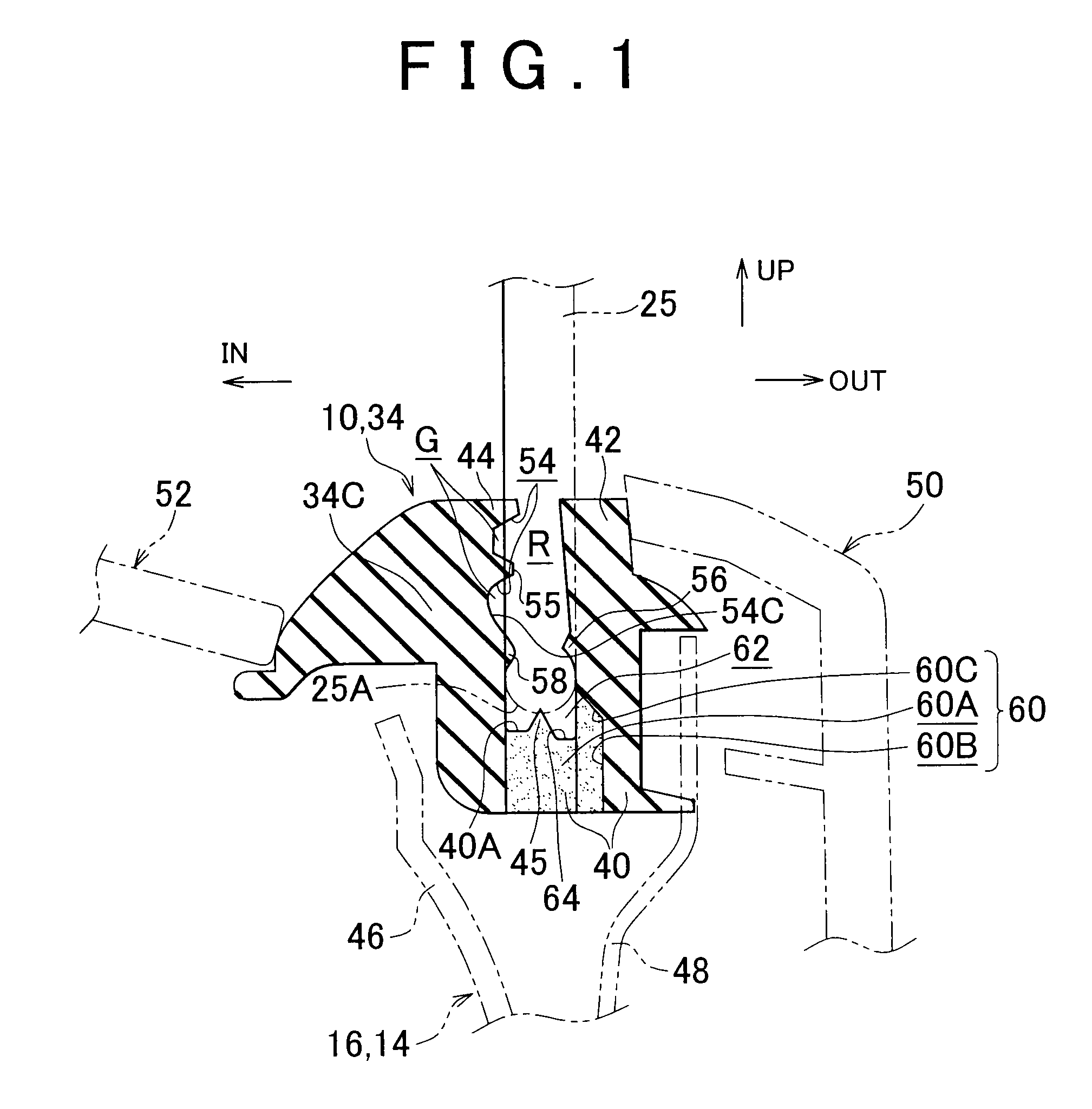
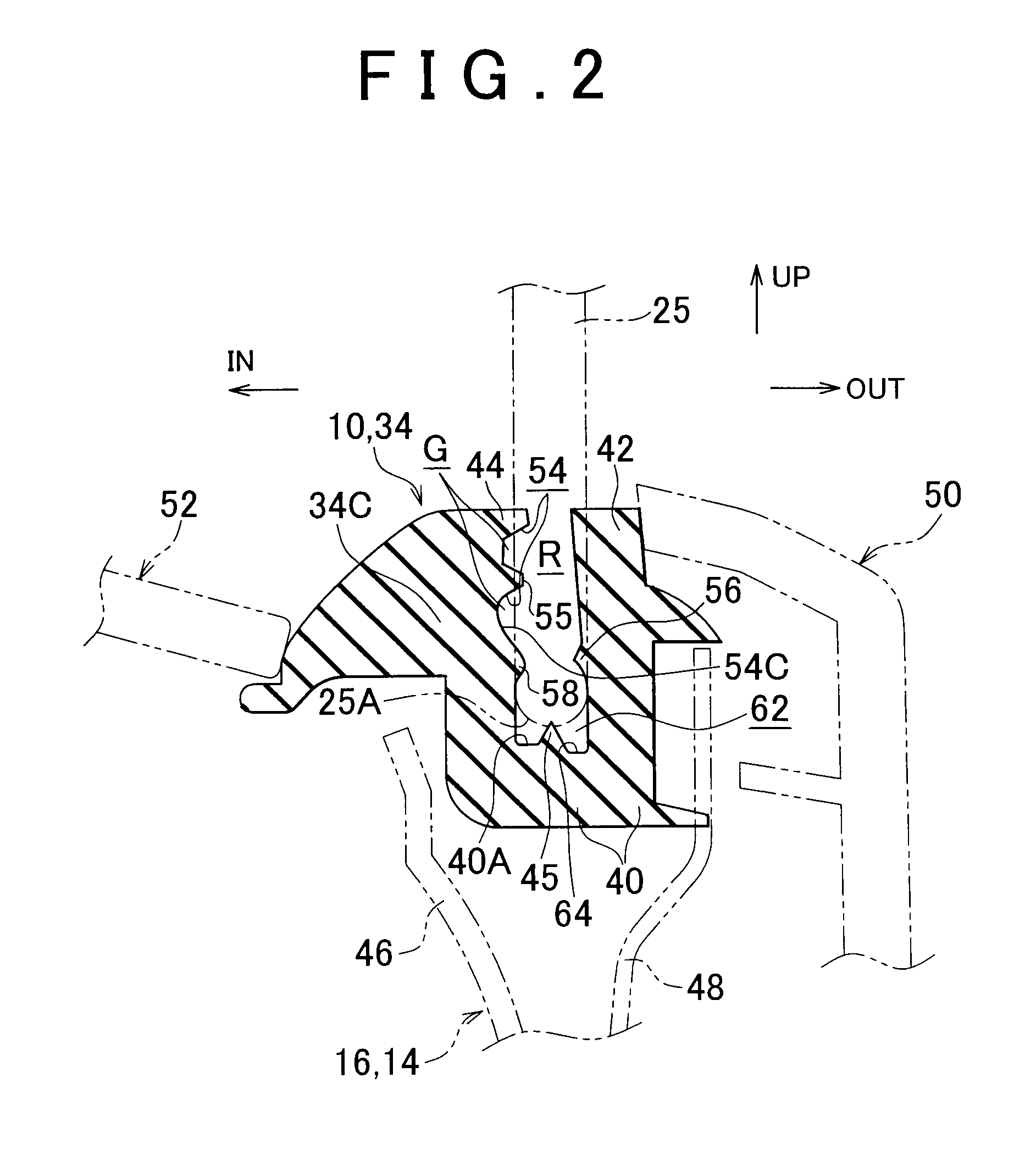
[0008]According to the feature or example embodiment described above, the bottom wall, the outer wall and the inner wall produce a substantially C-shaped cross section, and the weather strip seals the channel around the window glass (along the surface thereof), by sandwiching the
peripheral portion of the window glass between the outer wall and the inner wall. In this sealed state, a gap (space) is created by the side groove between the window glass and the at least one of the outer wall or the inner wall. Thus, with the present weather strip structure, entrance of water into the interface between the window glass and the outer wall or the inner wall due to capillarity, for example, is effectively prevented. In other words, it is possible to effectively prevent water from entering the inside of the vehicle through the interface between the weather strip and the window glass.
[0010]According to the second feature or example embodiment described above, the bottom wall, the outer wall and the inner wall produce a substantially C-shaped cross section, and the weather strip seals the channel around the window glass (along the surface thereof), by sandwiching the
peripheral portion of the window glass between the outer wall and the inner wall. In this sealed state, the lip protruding from one or each of the outer wall and the inner wall is in pressure contact (elastic contact) with the window glass. Thus, with the present weather strip structure, higher sealing pressure against the window glass is achieved, and the degree of sealing the water
entrance channel between the weather strip and the window glass is increased. In particular, because the lip disposed between the bottom wall and the free end of the outer wall or the inner wall is not exposed on the open end side of the weather strip structure, the sealing portion is protected, and the lip can exhibit the required degree of sealing. Thus, it is possible to effectively prevent water from entering into the inside of the vehicle through the interface between the weather strip and the window glass.
[0011]With the above features, because a seal is provided at a location spaced from the open end of the weather strip, this seal can avoid the high pressures to which the open end (at the free ends of the inner and outer walls) might be exposed, and thus sealing is improved. However, under certain conditions, water could nevertheless pass through the improved seal arrangement. Thus, as an alternative to the above improved seal features, or more preferably in addition to one or more of the improved seal features, the present invention also provides improved arrangements for handling water that could pass between the window glass and one of the walls of the weather strip structure. Such additional or alternate features can include, for example, a drainage through hole and / or a drainage groove as discussed herein.
[0013]According to the third feature or example described above, the bottom wall, the outer wall and the inner wall produce a substantially C-shaped cross section, and the weather strip seals the channel at a lower portion of the window glass (along the surface thereof), by sandwiching a lower edge portion of the window glass between the outer wall and the inner wall. The water that enters through the interface between the outer wall and the window glass is drained out through the through hole in the bottom wall. In a preferred example of the present weather strip structure, the through hole is offset toward the outside of the vehicle body with respect to the lower end face of the window glass, which prevents the end face of the window glass from closing the through hole. Thus, with the present weather strip structure, required drainage capacity provided by the through hole is ensured. Accordingly, it is possible to effectively prevent water from entering the inside of the vehicle through the interface between the weather strip and the window glass.
[0015]According to the fourth feature or example described above, the bottom wall, the outer wall and the inner wall produce a substantially C-shaped cross section, and the weather strip seals the channel at a lower portion of the window glass (along the surface thereof), by sandwiching a lower edge portion of the window glass between the outer wall and the inner wall. The water that enters through the interface between the outer wall and the window glass is led to the through hole via the bottom groove and is drained out through the through hole. In the present weather strip structure, the bottom wall (the part thereof between the inner and outer walls) that has substantially the same width as that of the window glass is provided with the bottom groove (for example in the form of a concave portion), which prevents the lower end portion of the window glass from occupying the bottom groove. Thus, with the present weather strip structure, required drainage capacity provided by the bottom groove and the through hole is ensured. Accordingly, it is possible to effectively prevent water from entering the inside of the vehicle through the interface between the weather strip and the window glass.
[0017]As described above, with the weather strip structure according to the invention, it is possible to effectively prevent water from entering the inside of the vehicle through the interface between the weather strip and the window glass.

