Apparatus for stacking electrode plates

a technology of electrode plates and apparatus, applied in the manufacture of secondary cells, domestic applications, variable height tables, etc., can solve the problems of increasing the waiting period, affecting the efficiency of electrode plates, and relatively high material consumption, so as to improve the low efficiency

Active Publication Date: 2012-11-20
KUO LUNG +1
View PDF18 Cites 6 Cited by
  • Summary
  • Abstract
  • Description
  • Claims
  • Application Information

AI Technical Summary

Benefits of technology

[0018]A primary objective of the present invention is to improve the low efficiency for arranging the electrode plates on the electrode plate support one by one manually before acid dipping.

Problems solved by technology

The conventional sealed lead-acid batteries have the following shortcomings:(1) The gird is made by pouring molten lead ingots into a mold, and however, material consumption is relatively high by using this process.(2) If the electrode plates are vertically arranged, the electrolyte stratification will occur.(3) The electrode plates are secured in place by the fixing rods located on the two sides of the electrolysis tank, and however, the active substances of the electrode plates easily drop off due to impact and vibration.(4) The manufacturing processes involve repeatedly drying and maturing steps so that it requires a longer period to complete the processes, and the longer period delays the capital flow and increases the waiting period of the products in the market.(5) The grid is made of solid lead alloy, and the lead ingots for the proper series and / or parallel connections of the electrodes are required, and thereby material consumption is relatively high.(6) Lead vapor is released in the process of melting lead ingots, which can pollute the environment when ventilation is not adequate.(7) The ratio of the energy output of a battery to its weight (33 wh / kg) is low, and the battery cycle life is only about 300 cycles due to the anti-vibration structure of the battery, and the battery charge time is too long which requires about 6 to 8 hours.
However, the efficiency to arrange the electrode plates on the electrode plate support one by one manually is too low.

Method used


Image

  • Apparatus for stacking electrode plates
  • Apparatus for stacking electrode plates
  • Apparatus for stacking electrode plates

Examples


Embodiment Construction

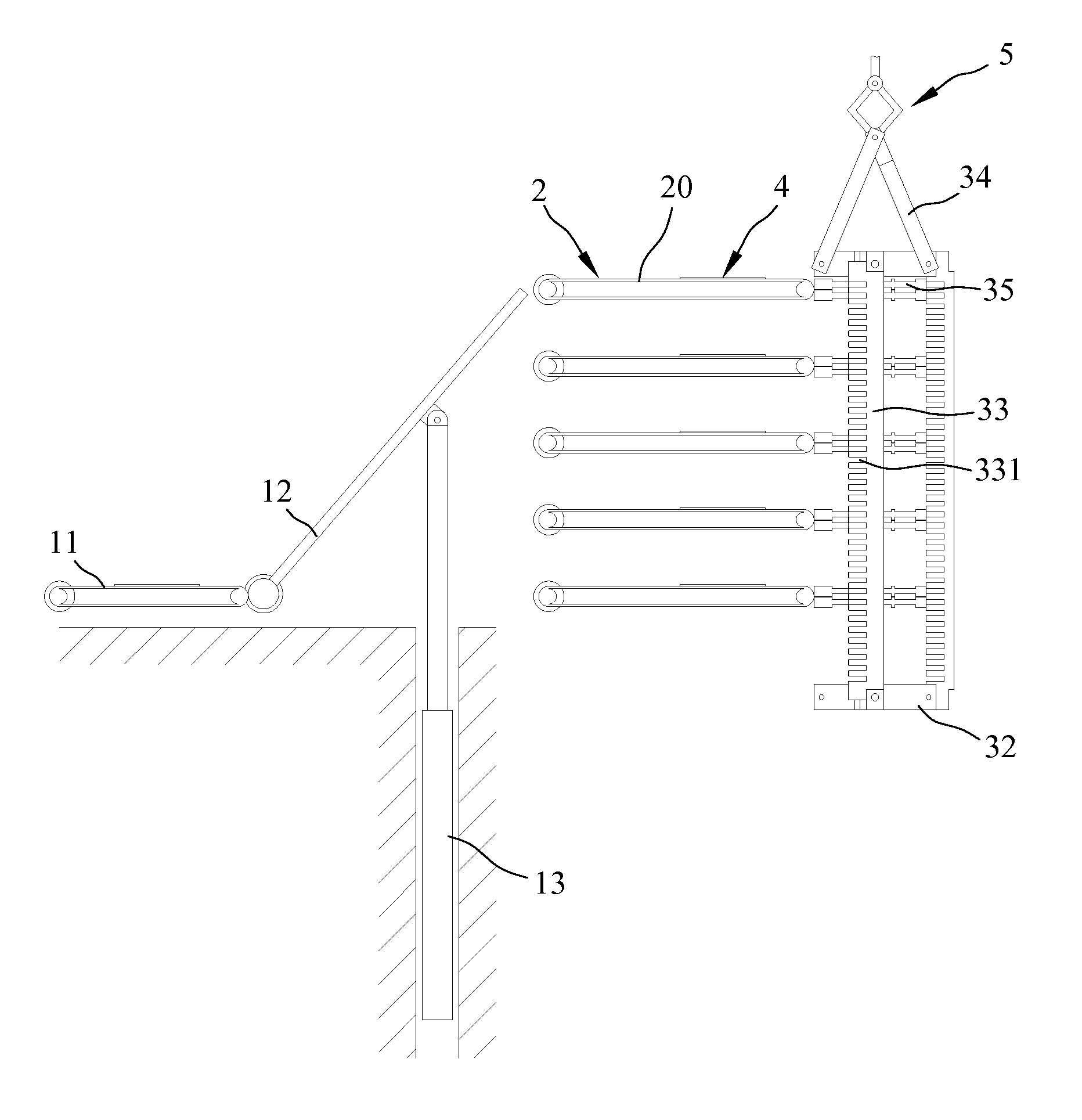
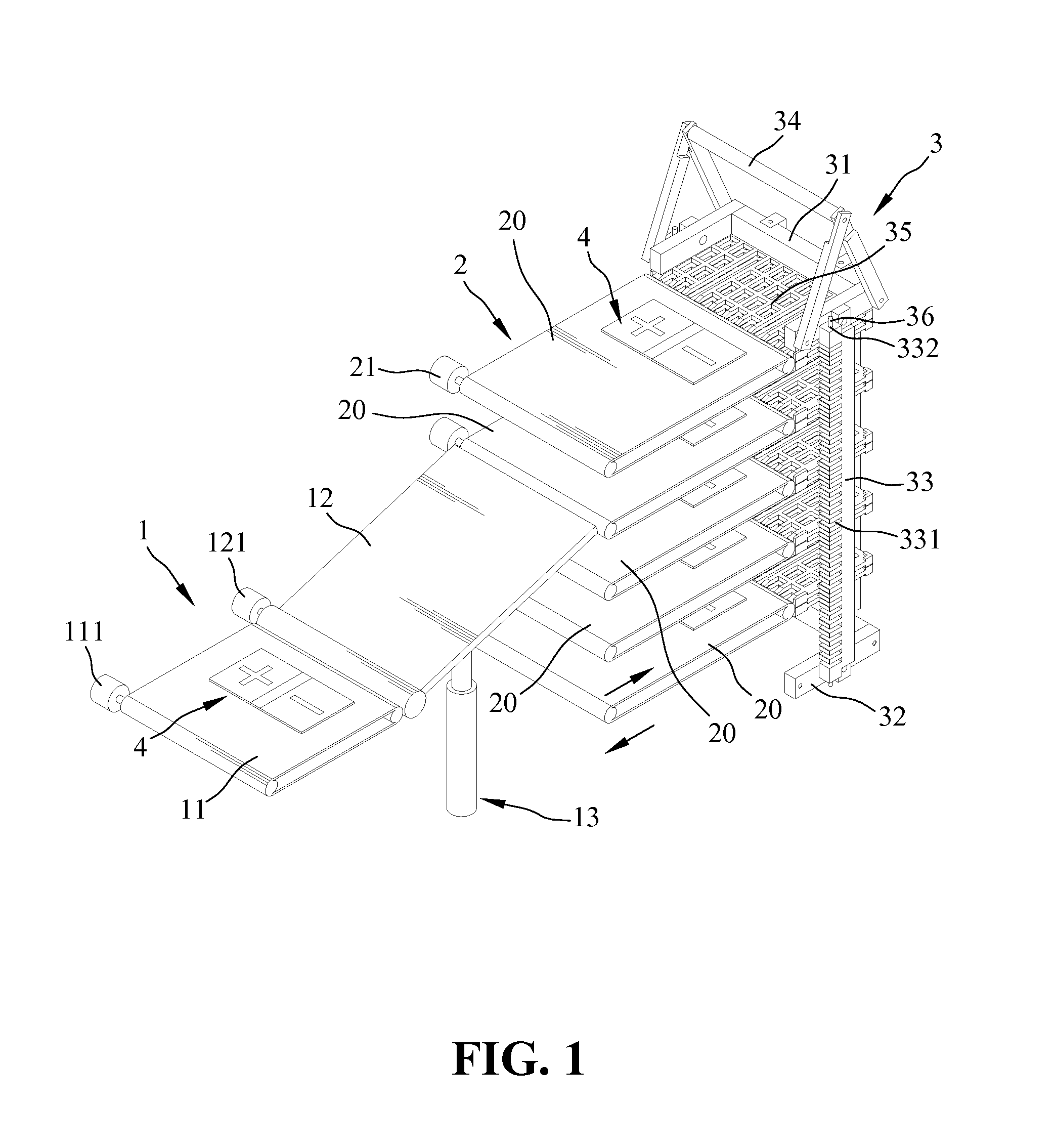
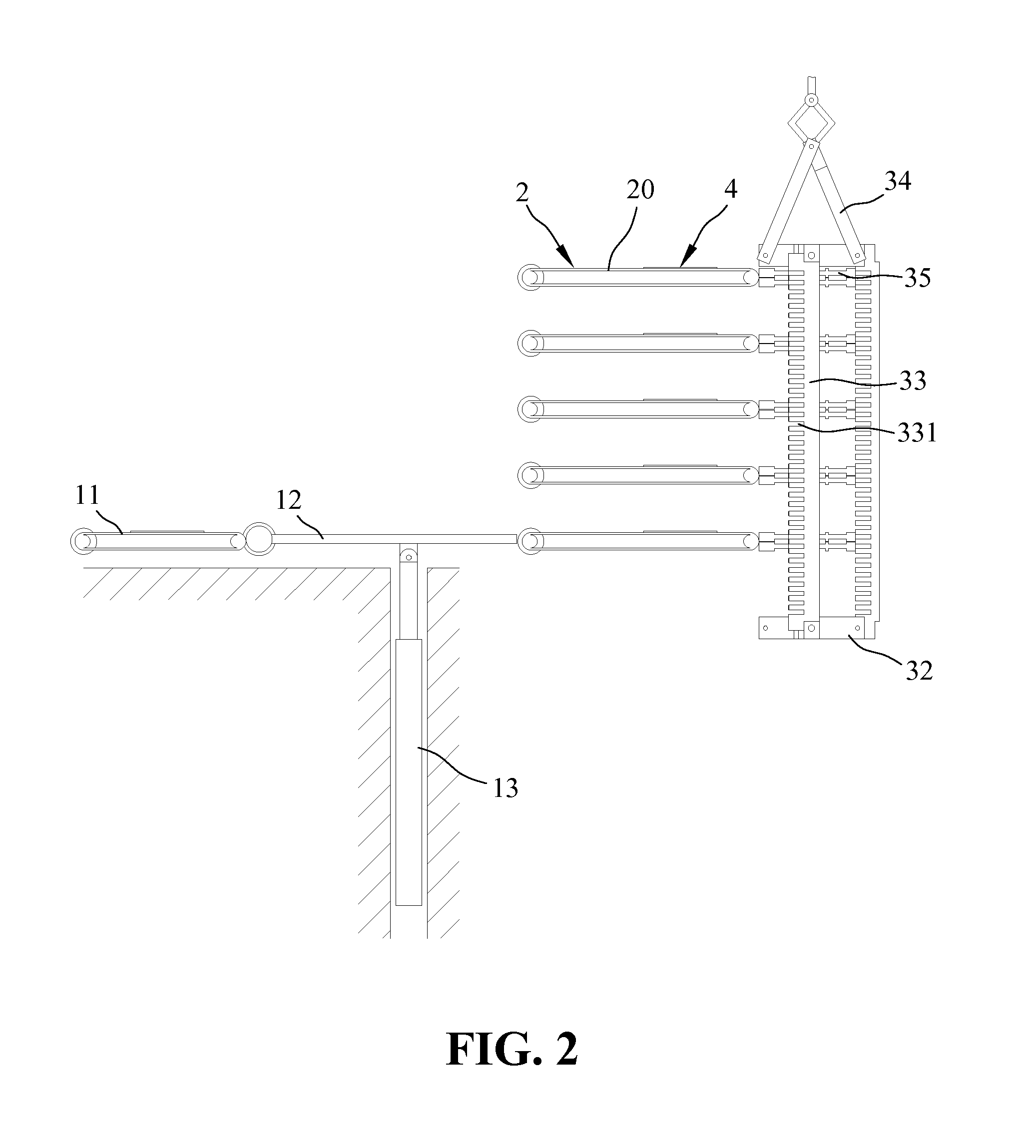
[0032]With reference to the drawings and in particular to FIG. 1, an apparatus for stacking electrode plates according to the present invention comprises a first transfer conveyor unit 1, a second transfer conveyor unit 2, and an electrode plate support 3. The first transfer conveyor unit 1 comprises an addressing conveyor 11 and a movable conveyor 12 which is located at the output end of the first transfer conveyor unit 1. The addressing conveyor 11 can be a conveyor belt which is driven by a first motor 111, and the movable conveyor 12 can be a conveyor belt driven by a second motor 121. The movable conveyor 12 has one end that is adjacent to the addressing conveyor 11 and is pivotably connected to the ground, and a power unit 13 is connected to the proper position at the underside of the movable conveyor 12. The power unit 13 drives the movable conveyor 12 upward or downward so as to vary the angle between the movable conveyor 12 and the addressing conveyor 11. The power unit 13 ...


PUM


Abstract

An apparatus for stacking electrode plates includes a first and second transfer conveyor units, and an electrode plate support. The first transfer conveyor unit includes an addressing conveyor and a movable conveyor, and a power unit drives the movable conveyor upward and downward to vary the angle between the movable conveyor and the addressing conveyor. The second transfer conveyor unit has a plurality of conveyors located at different heights. The electrode plate support has a plurality of support plates which are placed vertically parallel to one another. The electrode plate support is moved upward and downward in a vertical direction via a conveyor device to move the support plates to positions adjacent to their own corresponding conveyors of the second transfer conveyor unit at different heights, and each of the support plates accepts an electrode plate from its own corresponding conveyor of the second transfer conveyor unit.

Description

BACKGROUND OF THE INVENTION[0001]1. Field of the Invention[0002]The present invention relates to an apparatus for stacking electrode plates, which can automatically and quickly stack the electrode plates for batteries.[0003]2. The Prior Arts[0004]The conventional sealed lead-acid batteries have the following shortcomings:[0005](1) The gird is made by pouring molten lead ingots into a mold, and however, material consumption is relatively high by using this process.[0006](2) If the electrode plates are vertically arranged, the electrolyte stratification will occur.[0007](3) The electrode plates are secured in place by the fixing rods located on the two sides of the electrolysis tank, and however, the active substances of the electrode plates easily drop off due to impact and vibration.[0008](4) The manufacturing processes involve repeatedly drying and maturing steps so that it requires a longer period to complete the processes, and the longer period delays the capital flow and increas...

Claims


Application Information

Patent Timeline
Patent Type & Authority Patents(United States)
IPC IPC(8): B65G47/46
CPCH01M10/0404H01M10/14B65G47/647H01M10/06Y02E60/126Y02E60/10
Inventor KUO, LUNGKUO, CHIA-SHOU
Owner KUO LUNG
Why Eureka
Try Eureka