
Method for manufacturing semiconductor device

a semiconductor and manufacturing method technology, applied in the manufacture of electrode systems, electric discharge tubes/lamps, discharge tubes luminescnet screens, etc., can solve the problems of difficult to form partition walls, short circuits are easy to occur, and the length of partition walls is changed in each substrate or even over the same substrate, etc., to achieve excellent reproducibility, simple method, and low cost

Inactive Publication Date: 2012-11-20
SEMICON ENERGY LAB CO LTD
View PDF60 Cites 2 Cited by
  • Summary
  • Abstract
  • Description
  • Claims
  • Application Information

AI Technical Summary

Benefits of technology

[0008]When a taper angle of a partition wall is too big, a film formed thereover becomes thin; therefore, a short-circuit might be easily caused. In addition, when a film over a partition wall is thin, physical strength of the film is likely to be low. Furthermore, when a taper angle of a partition wall is too big, moisture is likely to enter therefrom.
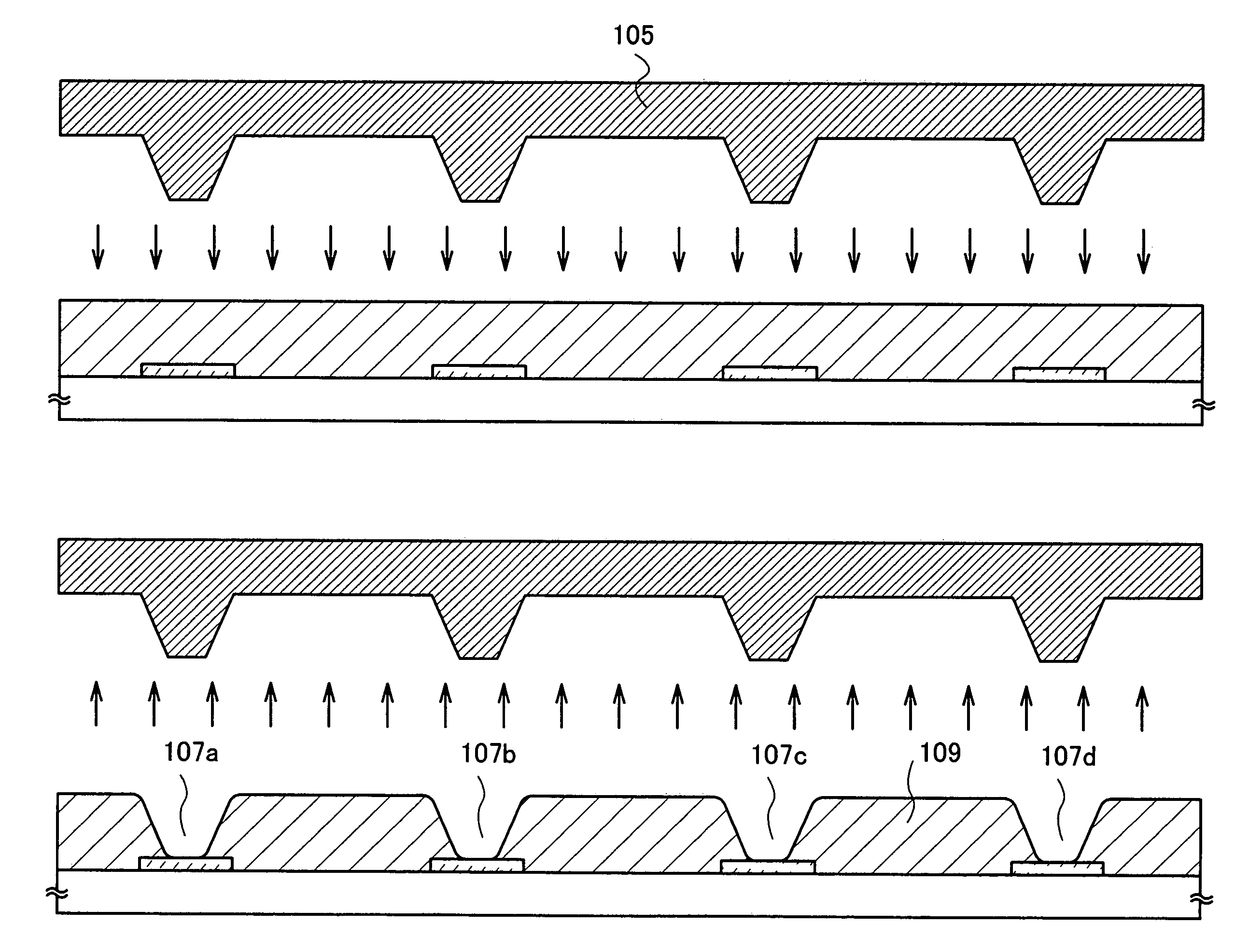
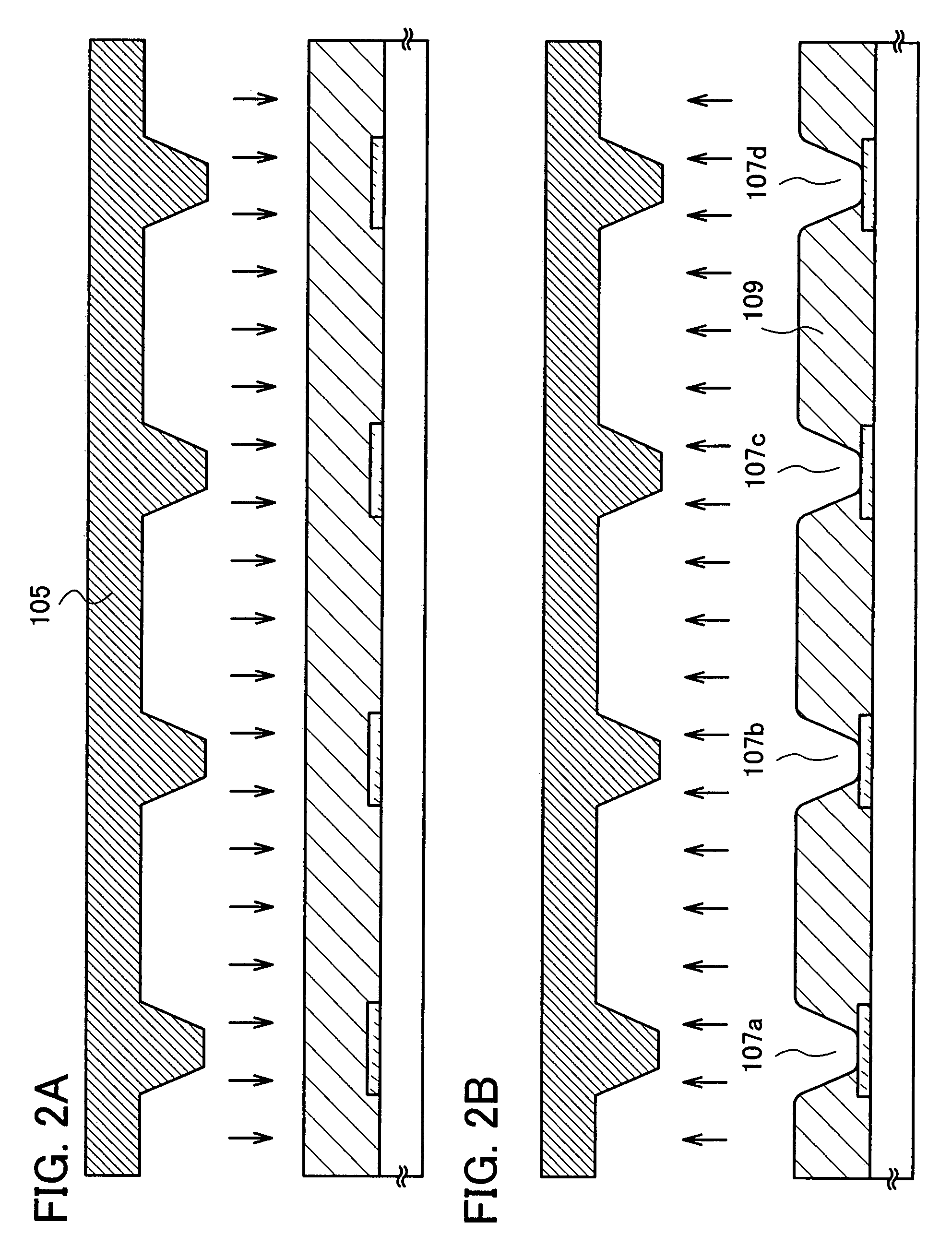
[0025]When a taper angle of a partition wall is 20 to 50° and edges of a top and bottom of the partition wall are rounded, moisture can be prevented from entering and a short-circuit can be prevented. Accordingly, a highly-reliable light-emitting display device can be obtained.

Problems solved by technology

When a partition wall is formed by dry etching or wet etching, there is a defect in that the length of the partition wall is changed in each substrate or even over the same substrate.
Moreover, by a method in which a partition wall is formed by dry etching or wet etching, it is difficult to form a partition wall with purposeful control of a taper angle of the partition wall.
When a taper angle of a partition wall is too big, a film formed thereover becomes thin; therefore, a short-circuit might be easily caused.
In addition, when a film over a partition wall is thin, physical strength of the film is likely to be low.
Furthermore, when a taper angle of a partition wall is too big, moisture is likely to enter therefrom.
When the film is ruptured, moisture is likely to enter therefrom or a short-circuit is likely to be caused.

Method used


Image

  • Method for manufacturing semiconductor device
  • Method for manufacturing semiconductor device
  • Method for manufacturing semiconductor device

Examples


embodiment 1

[Embodiment 1]

[0084]An example of using a manufacturing method of a semiconductor device of the present invention will be explained with reference to FIGS. 4A to 4D, FIGS. 5A to 5C, FIGS. 6A to 6C, FIGS. 7A and 7B, FIGS. 8A and 8B, FIGS. 9A and 9B, FIG. 10, FIG. 11, and FIG. 12.

[0085]First, as shown in FIG. 4A, a base film 502 is formed over a substrate 501. As the substrate 501, for example, a glass substrate such as barium borosilicate glass or alumino borosilicate glass, a quartz substrate, a stainless steel substrate, or the like can be used. In addition, a substrate made of plastic typified by PET (polyethylene terephthalate), PES (polyethersulfone), or PEN (polyethylene naphthalate), or a substrate made of a flexible synthetic resin such as acrylic can be used.

[0086]The base film 502 is provided in order to prevent an alkali metal such as Na or an alkaline earth metal contained in the substrate 501 from diffusing into a semiconductor film and having an adverse effect on charac...

embodiment 2

[Embodiment 2]

[0186]In this embodiment, an example in which the present invention is applied to an inorganic EL element will be explained with reference to FIGS. 13A to 13C and FIGS. 14A to 14C.

[0187]A light-emitting element utilizing electroluminescence is distinguished by whether a light-emitting material is an organic compound or an inorganic compound. In general, the former is referred to as an organic EL element and the latter is referred to as an inorganic EL element. The example in which an organic EL element is used in the present invention is described in Embodiment 1.

[0188]The inorganic EL element is classified into a dispersion type inorganic EL element and a thin film type inorganic EL element, depending on its element structure. The former and the latter are different in that the former has an electroluminescent layer in which particles of a light-emitting material are dispersed in a binder, whereas the latter has an electroluminescent layer formed of a thin film of a l...

embodiment 3

[Embodiment 3]

[0224]As electronic appliances to which the present invention is applied, the following can be given: a camera such as a video camera or a digital camera; a goggle type display, a navigation system; an audio reproducing device (such as a car audio component set); a computer; a game machine; a portable information terminal (such as a mobile computer, a cellular phone, a portable game machine, or an e-book reader); an image reproducing device provided with a recording medium (specifically, a device for reproducing a recording medium such as a digital versatile disc (DVD) and having a display for displaying the reproduced image), and the like.

[0225]Specific examples of the electronic appliances are shown in FIG. 15, FIG. 16, FIGS. 17A and 17B, FIG. 18, FIG. 19, FIG. 20, and FIGS. 21A to 21E.

[0226]FIG. 15 shows an EL module in which a display panel 301 and a circuit substrate 311 are combined. Over the circuit substrate 311, a control circuit 312, a signal division circuit...


PUM

PropertyMeasurementUnit
taper angleaaaaaaaaaa
luminanceaaaaaaaaaa
cross-sectional taper angleaaaaaaaaaa

Abstract

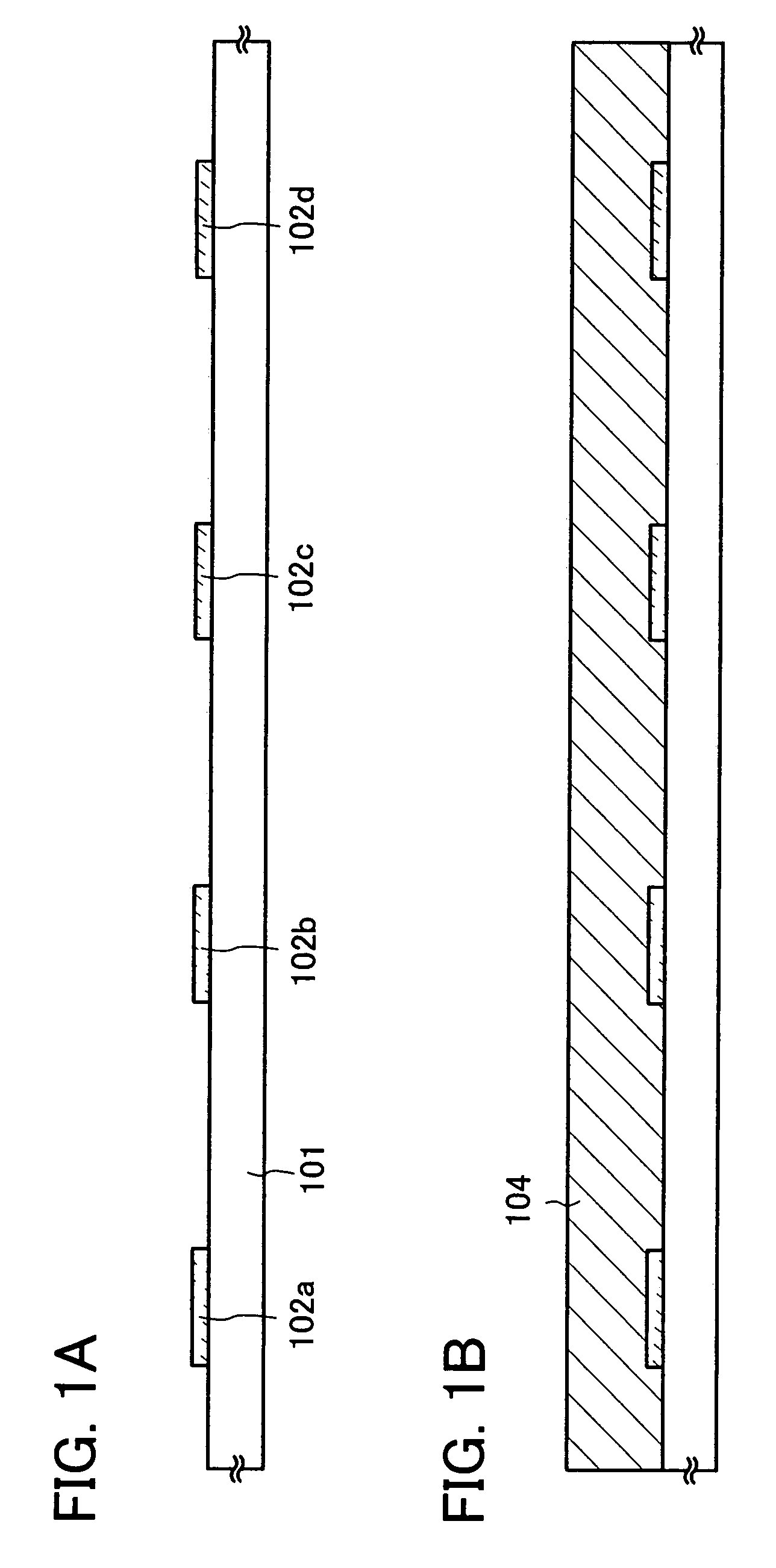
An object is to provide a semiconductor device with excellent reproducibility which is manufactured at low cost. A manufacturing method of a semiconductor device includes steps of forming a first electrode over a substrate; forming an insulating layer over the substrate and the first electrode; pressing a mold against the insulating layer to form an opening in the insulating layer; separating the mold from the insulating layer in which the opening is formed; hardening the insulating layer in which the opening is formed to form a partition wall; forming a light-emitting layer over the first electrode and the partition wall; and forming a second electrode over the light-emitting layer. The insulating layer contains a thermosetting resin material or a light curable resin material. The partition wall has a cross-sectional taper angle of 20 to 50°, and edges of a top and bottom thereof are rounded.

Description

TECHNICAL FIELD[0001]The present invention relates to a semiconductor device and a method for manufacturing the semiconductor device.BACKGROUND ART[0002]Development of a light-emitting device using a light-emitting element in which a layer including a light-emitting layer is included between a pair of electrodes and which emits light with current applied between the electrodes has been expanded. Such a light-emitting device is more advantageous to reduction in thickness and weight, in comparison with other display devices referred to as thin display devices, has a high level of visibility because of a self-luminous display device, and has fast response speed. Therefore, the light-emitting device has been actively developed as a next-generation display device, and part of the light-emitting device has been put to practical use.[0003]As the above-described light-emitting device, a light-emitting display device is given, in which a light-emitting element in which a layer containing an ...

Claims


Application Information

Patent Timeline
Patent Type & Authority Patents(United States)
IPC IPC(8): H01L27/32H01L27/28
CPCH01L27/3246H01L51/56H01L27/3283H10K59/122H10K59/173H10K71/00H01L2224/80862H01L2224/80874
Inventor FUJII, TERUYUKI
Owner SEMICON ENERGY LAB CO LTD
Learn More