

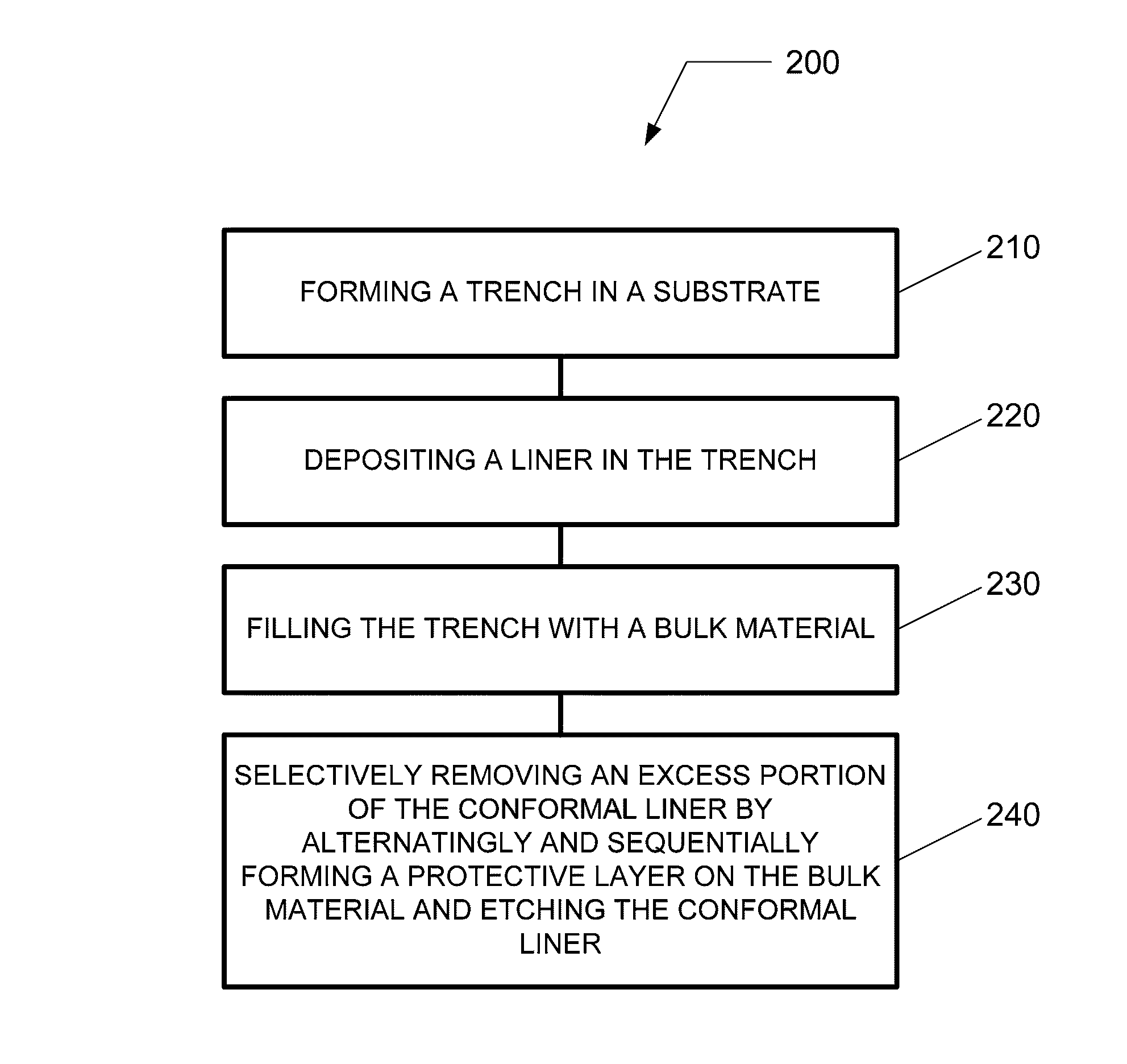
Deep trench liner removal process
a liner and trench technology, applied in the field of liner removal process, can solve the problems of undesirable recesses in bulk fill materials, current high-k dielectric materials that are currently being evaluated, and the practicability of current high-k dielectric materials, and achieve the effect of reducing or minimizing damage to bulk fill materials in the trench
- Summary
- Abstract
- Description
- Claims
- Application Information
AI Technical Summary
Benefits of technology
Problems solved by technology
Method used
Image

Examples
Embodiment Construction
[0018]In the following description, for purposes of explanation and not limitation, specific details are set forth, such as a particular geometry of a processing system, descriptions of various components and processes used therein. However, it should be understood that the invention may be practiced in other embodiments that depart from these specific details.
[0019]Similarly, for purposes of explanation, specific numbers, materials, and configurations are set forth in order to provide a thorough understanding of the invention. Nevertheless, the invention may be practiced without specific details. Furthermore, it is understood that the various embodiments shown in the figures are illustrative representations and are not necessarily drawn to scale.
[0020]Reference throughout this specification to “one embodiment” or “an embodiment” or variation thereof means that a particular feature, structure, material, or characteristic described in connection with the embodiment is included in at ...
PUM
| Property | Measurement | Unit |
|---|---|---|
| dielectric constant | aaaaa | aaaaa |
| dielectric constant | aaaaa | aaaaa |
| size | aaaaa | aaaaa |
Abstract
Description
Claims
Application Information