
Apparatus for measuring fluorescence lifetime

a technology of fluorescence lifetime and apparatus, which is applied in the direction of fluorescence/phosphorescence, luminescent dosimeters, optical radiation measurement, etc., can solve the problems of tscpc having a long measurement time, the scheme of fluorescence lifetime measurement for wide-field microscopy cannot be applied to high-resolution three-dimensional scanning microscopy such as confocal, and the effect of high measurement speed

Active Publication Date: 2012-11-20
INTEKPLUS
View PDF4 Cites 4 Cited by
  • Summary
  • Abstract
  • Description
  • Claims
  • Application Information

AI Technical Summary

Benefits of technology

[0025]It is a technical problem of the present invention to provide an apparatus for measuring a fluorescence lifetime that is capable of accurately and precisely measuring a fluorescence lifetime at a high measurement speed through an easy calculation and suitable for a fluorescence lifetime imaging microscope acquiring an image based on a spatial distribution of the measured fluorescence lifetime.
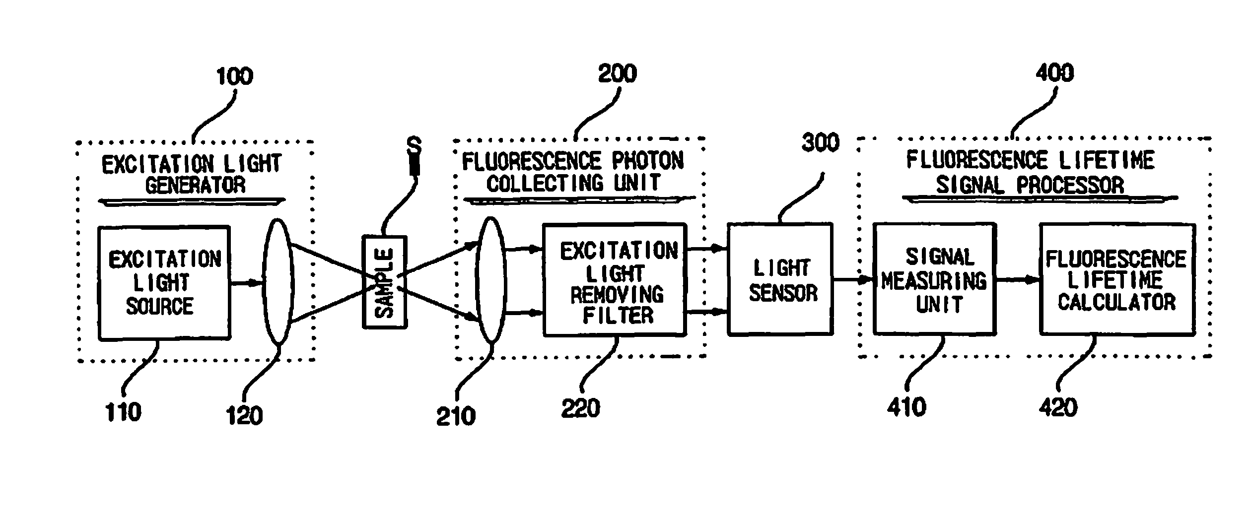
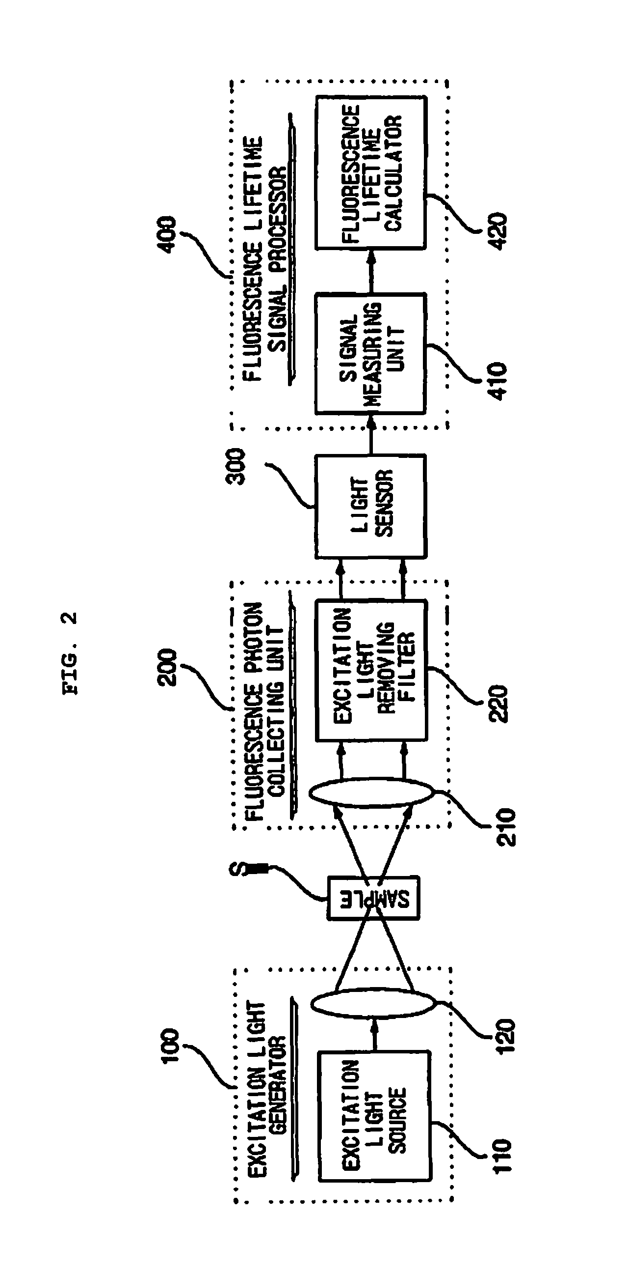
[0031]The fluorescence photon collecting unit may include: a fluorescence photon collecting lens that collects the generated fluorescence photons; and an excitation light removing filter for preventing the excitation light from being delivered to the light sensor.

Problems solved by technology

Presence of such a competing pathway can decrease the fluorescence emission efficiency and the fluorescence lifetime as compared to the case of the absence.
However, the scheme of fluorescence lifetime measurement for the wide-field microscopy can not be applied to high-resolution three-dimensional scanning microscopy such as a confocal microscopy due to the nature of parallel signal acquisitions.
However, the TSCPC has a problem of a long measurement time, which is a fundamental problem in the single photon counting method.
If the time interval between the excitation light pulses is not sufficiently longer than the fluorescence lifetime, the decay waveforms of two adjacent fluorescence emissions may overlap, making it impossible to obtain an accurate value of the fluorescence lifetime.
This property of a low measurement speed of the TCSPC limits the image acquisition speed of the scanning FLIM microscope that uses the TCSPC for fluorescence lifetime determination.
It is a serious obstacle in practical applications of the FLIM microscopy, especially for continuous observations of live organisms.

Method used


Image

  • Apparatus for measuring fluorescence lifetime
  • Apparatus for measuring fluorescence lifetime
  • Apparatus for measuring fluorescence lifetime

Examples


Embodiment Construction

[0045]Hereinafter, exemplary embodiments of the present invention will be described with reference to the accompanying drawings. Like components are denoted by like reference numerals in the following description and throughout the accompanying drawings and therefore, the duplicated description thereof will not be repeated. Also, the concrete description of the known function or configuration will not be repeated in the description of the present invention when making the subject matter of the present invention unnecessarily obscure.

[0046]The principle of fluorescence lifetime measurement according to the present invention will be described at first, prior to the explanation of the exemplary embodiments of the present invention.

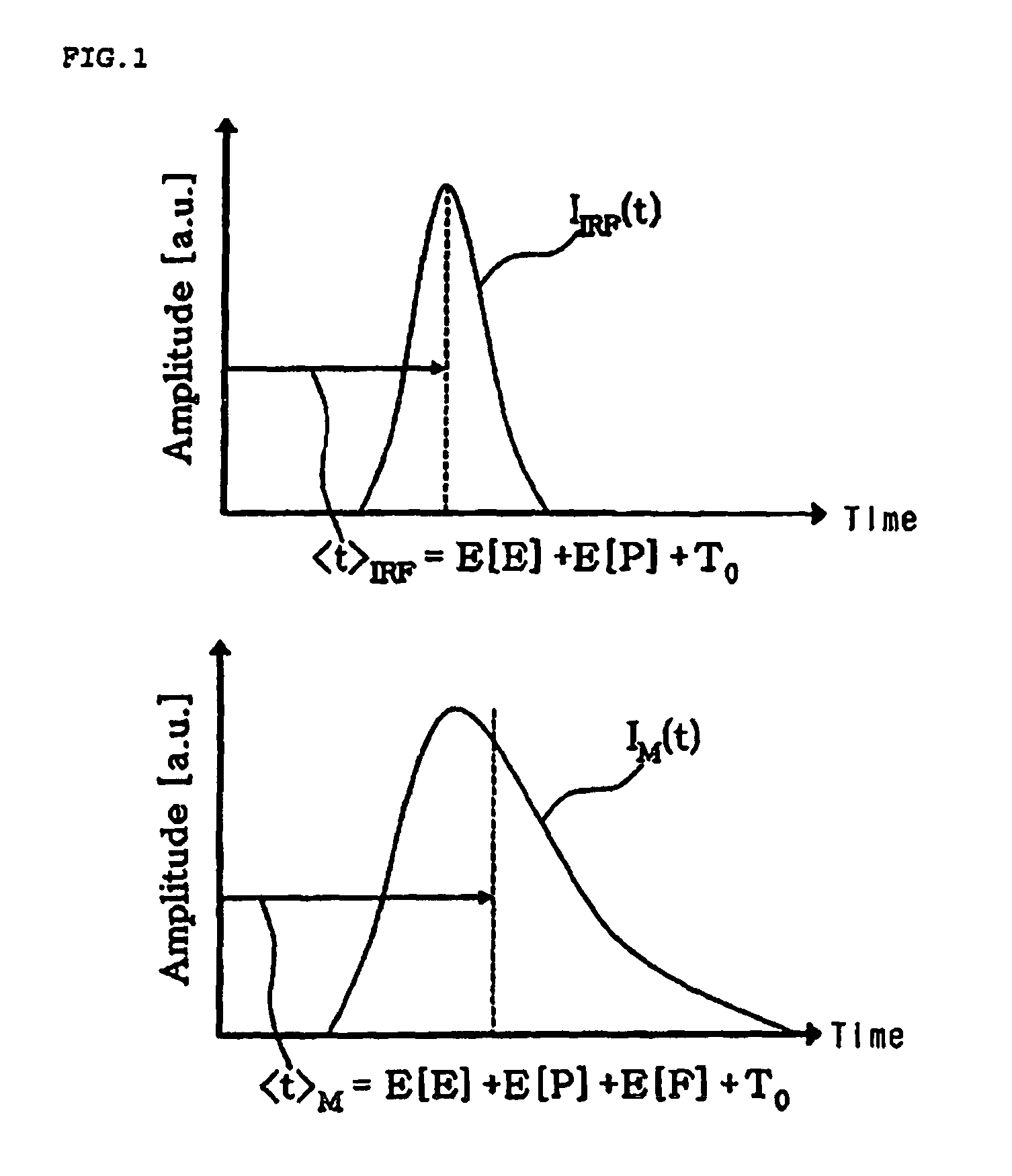
[0047]The most intuitive method for measuring a fluorescence lifetime is the method that inputs excitation light of a short pulse form into a sample and measures a time waveform of emitted fluorescence intensity with a high-speed light sensor. A pulse-type la...


PUM

PropertyMeasurementUnit
fluorescence lifetimeaaaaaaaaaa
average frequencyaaaaaaaaaa
fluorescence lifetimeaaaaaaaaaa

Abstract

Disclosed is an apparatus for measuring a fluorescence lifetime. The apparatus for measuring the fluorescence lifetime comprises an excitation light generator that generates excitation light to be irradiated on a sample including fluorescence molecules; a fluorescence photon collecting unit that collects a plurality of fluorescence photons generated by irradiating the excitation light on the sample; a light sensor that converts the collected fluorescence photons into a fluorescence electrical signal; and a fluorescence lifetime signal processor that determines the fluorescence lifetime by calculating the average time of the fluorescence electrical signal with respect to a predetermined apparatus delay time. According to the above configuration, the present invention can accurately and precisely measure a fluorescence lifetime in a short measurement time by easy calculation.

Description

BACKGROUND OF THE INVENTION[0001]1. Technical Field[0002]The present invention relates to an apparatus for measuring a fluorescence lifetime, and more specifically to an apparatus for precisely measuring a fluorescence lifetime that is an inherent optical characteristic of fluorescence materials in a short measurement time. This invention provides a means to acquire the fluorescence lifetime information for high-speed measurement applications such as a fluorescence lifetime imaging microscope that acquires an image of spatial distribution of the fluorescence lifetime for a fluorescent sample.[0003]2. Related Art[0004]A molecule can absorb an incident photon as a result of electronic transition from the ground state to a higher energy level when the molecule has an electronic state with the potential energy that matches to the energy of the incident photon. A fluorescence emission phenomenon is observed for a certain kind of molecules, which emit fluorescence photons by the excited e...

Claims


Application Information

Patent Timeline
Patent Type & Authority Patents(United States)
IPC IPC(8): G01T1/10G01N21/61
CPCG01N21/6408G01N21/25G01N21/64
Inventor KIM, DUG YOUNGMOON, SUCBEILEE, DONGSOO
Owner INTEKPLUS
Learn More