Multilayer capacitor having low ESL and easily controllable ESR

a multi-layer capacitor and easy control technology, applied in the field of multi-layer capacitors, can solve the problems of large dv delay the supply of electrical charge to the ic, vibration, and noise containing many harmonic components, and achieve the effect of easy esr control

Active Publication Date: 2012-11-20
MURATA MFG CO LTD
View PDF30 Cites 12 Cited by
  • Summary
  • Abstract
  • Description
  • Claims
  • Application Information

AI Technical Summary

Benefits of technology

[0019]Accordingly, preferred embodiments of the present invention inexpensively and easily provide a multilayer capacitor that has a low ESL and is allowed to easily perform ESR control.

Problems solved by technology

A large variation in voltage of a power supply line in a power supply circuit due to the impedance of the power supply line or the ground destabilizes the operation of a driven circuit, causes interference between circuits coupled via the power supply circuit, or causes oscillation.
Therefore, noise containing many harmonic components tends to occur.
A large dV delays the supply of electrical charge to the IC.
However, it is known that when the ESR of a capacitor becomes too low, impedance mismatching between circuits occurs and thus damped vibration, called “ringing,” where the rising edge of a signal waveform is distorted, tends to occurs.
When ringing occurs, the IC may malfunction due to a disturbed signal.
Also, when the ESR of the capacitance becomes too low, the impedance frequency characteristic of the capacitor becomes too steep near the resonance frequency.
However, it is troublesome to prepare several types of resistance pastes in order to adjust the resistivity of the resistance material.
Also, when changing the composition of the resistance paste in order to adjust the resistivity, other factors such as the reactivity to the internal electrode and the adhesion to the capacitor body may be affected.
Also, there is a technical limit to thick application of a resistance paste, so there is a problem that performance of control, in particular, with a view toward increasing the ESR, prevented.

Method used


Image

  • Multilayer capacitor having low ESL and easily controllable ESR
  • Multilayer capacitor having low ESL and easily controllable ESR
  • Multilayer capacitor having low ESL and easily controllable ESR

Examples


Embodiment Construction

[0063]A first preferred embodiment of the present invention will be described with reference to FIGS. 1 to 4. The first preferred embodiment and second to sixth preferred embodiments according to the present invention to be described later relate to a first aspect of the present invention.

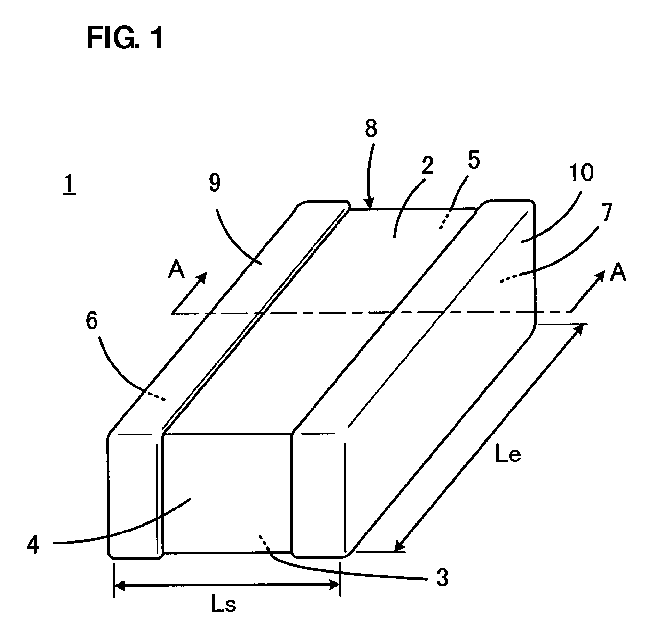
[0064]FIG. 1 is a perspective view showing an appearance of a multilayer capacitor 1 according to the first preferred embodiment. The multilayer capacitor 1 includes a capacitor body 8 preferably having a substantially rectangular parallelepiped shape and including first and second main surfaces 2 and 3 opposed to each other, first and second side surfaces 4 and 5 opposed to each other, and first and second end surfaces 6 and 7 opposed to each other. The multilayer capacitor 1 is of so-called “LW reverse type.” That is, the length direction dimension Le of each of the first and second end surfaces 6 and 7 is larger than the length direction dimension Ls of each of the first and second side surfaces...


PUM


Abstract

In a capacitor body, a single second capacitor unit is interposed between two first capacitor units. The width direction dimension of each of extended portions of first and second internal electrodes included in the first capacitor unit is larger than the width direction dimension of each of extended portions of third and fourth internal electrodes included in the second capacitor unit. The area of each of the respective portions of a first opposed portion of the first internal electrode and a second opposed portion of the second internal electrode, the respective portions being opposed to each other, is smaller than the area of each of respective portions of opposed portions of the third and fourth internal electrodes, the respective portions being opposed to each other. Thus, a multilayer capacitor has a characteristic that is a combination of a low-ESL characteristic of the first capacitor unit and a high-ESR characteristic of the second capacitor.

Description

BACKGROUND OF THE INVENTION[0001]1. Field of the Invention[0002]The present invention relates to a multilayer capacitor, in particular, to an improvement for easily controlling of the equivalent series resistance (ESR) of a multilayer capacitor.[0003]2. Description of the Related Art[0004]A large variation in voltage of a power supply line in a power supply circuit due to the impedance of the power supply line or the ground destabilizes the operation of a driven circuit, causes interference between circuits coupled via the power supply circuit, or causes oscillation. For this reason, typically, a decoupling capacitor is coupled between the power supply line and the ground. The decoupling capacitor reduces the impedance between the power supply line and the ground and restrains variations in power supply voltage or interference between the circuits.[0005]Incidentally, in recent years, signals have been speeded up in communication apparatuses such as cell phones and information proces...

Claims


Application Information

Patent Timeline
Patent Type & Authority Patents(United States)
IPC IPC(8): H01G4/005H01G4/228
CPCH01G4/012H01G4/30H01G4/38
Inventor TAKASHIMA, HIROKAZUUEOKA, HIROSHITAKAGI, YOSHIKAZU
Owner MURATA MFG CO LTD
Why Eureka
Try Eureka