Thermal postcombustion device and method for operating the same

a technology of post-combustion device and heat dissipation device, which is applied in the direction of solid fuel combustion, combustion types, lighting and heating apparatus, etc., can solve the problems of limited disposal of air containing adherent residues, reducing efficiency, and shutting down operation, so as to achieve the effect of shortening the tim

Inactive Publication Date: 2012-11-27
EISENMANN AG
View PDF12 Cites 0 Cited by
  • Summary
  • Abstract
  • Description
  • Claims
  • Application Information

AI Technical Summary

Benefits of technology

[0016]Furthermore, the addition of an additive, in particular a catalyst, the thermal effect of the hot clean air may assist in the removal of deposits and, in this manner, a shorter time may be achieved within which the thermal postcombustion device has to be operated in cleaning mode.

Problems solved by technology

With known thermal postcombustion devices of the aforementioned type, only a limited disposal of air containing adherent residues is possible, as deposits form on the colder regions of the heat exchanger surfaces which, over a period of time, block up the heat exchanger or at least reduce the efficiency thereof.
Shutting down the operation and costly cleaning operations are, therefore, required at regular time intervals.

Method used


Image

  • Thermal postcombustion device and method for operating the same
  • Thermal postcombustion device and method for operating the same
  • Thermal postcombustion device and method for operating the same

Examples


first embodiment

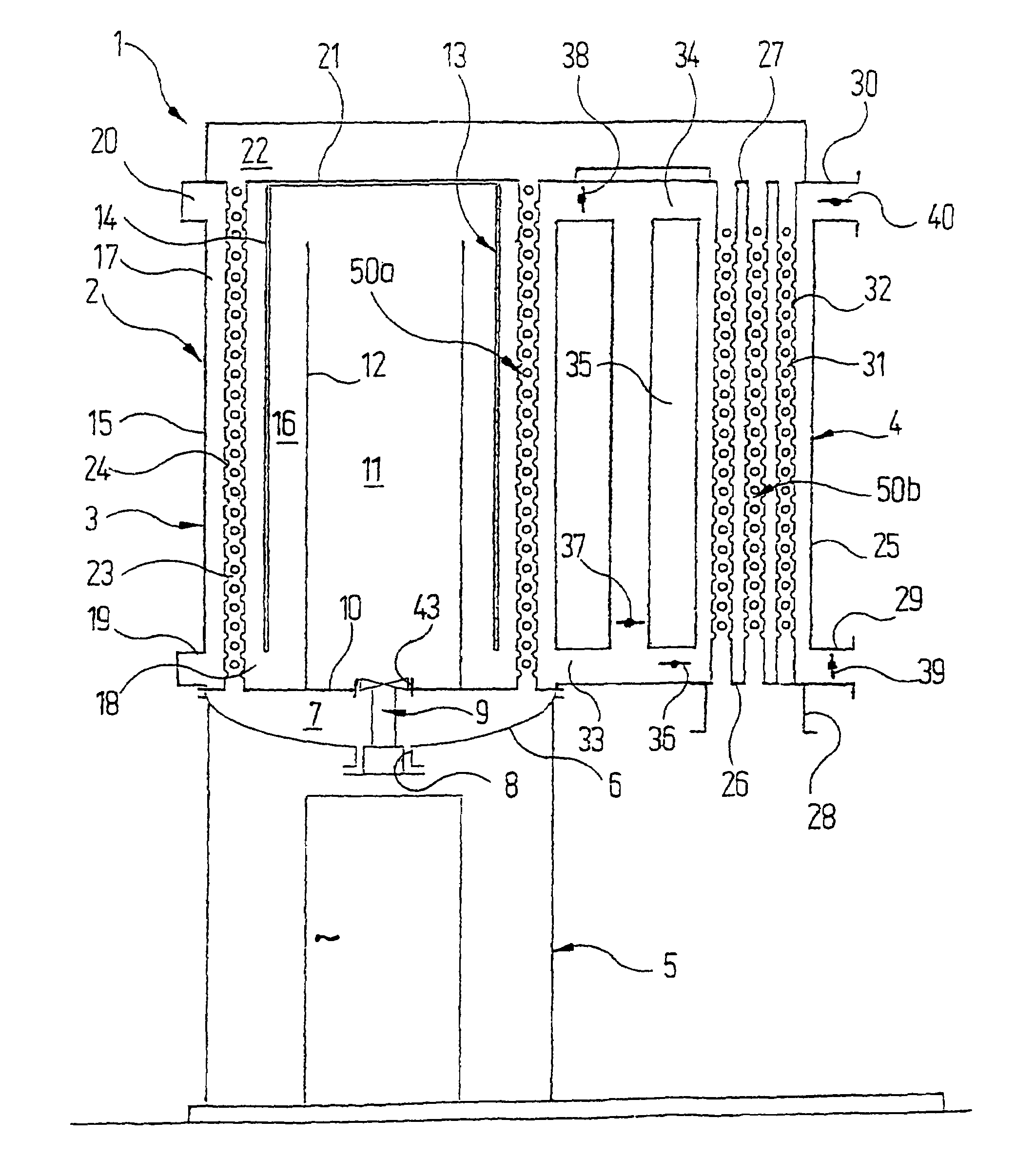
[0026]Reference is firstly made to FIGS. 1 to 3, in which a thermal postcombustion device is shown. Said thermal postcombustion device is able to carry out self-cleaning in two different operating modes, in which deposits originating from the exhaust air to be cleaned, are able to be removed.

[0027]The thermal postcombustion device is identified as a whole by the reference numeral 1. It includes a housing 2, which is made up of a main housing 3, a secondary housing 4 and an accessible substructure 5. The accessible substructure 5 is arranged coaxially below the main housing 3, and bears the main housing 3 as well as the secondary housing 4 connected thereto.

[0028]The cover 6 of the substructure 5 is arched downwards and at the same time forms the base of a plenum 7. A burner 9 is passed through a central opening 8 of the base 6 of the plenum 7. The components required for operating the burner 9 and not shown separately in the drawings, in particular the electrical control lines and p...

second embodiment

[0051]The construction of the second embodiment shown in FIGS. 4 and 5 of a thermal postcombustion device substantially coincides with the embodiment which was disclosed above with reference to FIGS. 1 to 3. Corresponding parts are, therefore, identified with the same reference numerals, plus 100.

[0052]The construction of the main housing 103, the substructure 105 of the upper air plenum 122 and the connecting lines 133, 134, 135, together with the components contained therein, coincides entirely with the conditions shown in FIGS. 1 to 3. Differences between the two embodiments are only in the construction of the secondary housing 104. This has, as FIGS. 4 and 5 make clear, only one single lower outlet 129 for clean gas, in which however no controllable flap needs to be arranged. At the axial height at which the lower connecting line 133 and the upper connecting line 134 discharge into the interior of the secondary housing 104, annular channels 141, 142 extend which are formed by co...

third embodiment

[0066]For the description of the mode of operation of a thermal postcombustion device 201, reference is firstly made to FIG. 6. This shows the position of the different flaps in an operating mode, in which the second preheat exchanger 250b′ operates in normal mode and the first preheat exchanger 250b is at a standstill. To this end, all flaps 236, 239 and 282 associated with the first preheat exchanger 250b are closed. The flap 236′ leading to the lower end region of the interior of the second secondary housing 204′ is also closed whilst the flaps 282′ and 239′ are open.

[0067]In these flap positions, the exhaust air to be cleaned flows via the inlet pipe 228′ into the heat exchanger pipes 231′ of the second preheat exchanger 250b′ via the upper plenum 222 through the heat exchanger pipes 223 of the primary heat exchanger 250a, through the lower plenum 207 into the combustion chamber 211, where the combustion of pollutants is initiated, via the annular spaces 216, 217 along the outer...


PUM


Abstract

A thermal postcombustion device includes, in a conventional manner per se, a housing, having an inlet for the exhaust air that is to be purified and an outlet for clean air. A combustion chamber is located inside the housing, and inside this combustion chamber, a heating device generates a temperature at which the pollutants carried by the exhaust air burn. In order to reduce the energy requirement, a heat exchanger is provided over which the exhaust air coming from the inlet is guided to the combustion chamber, and the clean air coming from the combustion chamber is guided to the outlet. In order to also be able to process exhaust air, which is loaded with adherent residues, for example, pitch vapors, a device is provided with which, during a purification mode, at least a portion of the clean air can be optionally fed past a section of the heat exchanger located closer to the combustion chamber and into another section of the heat exchanger located further from the combustion chamber. Deposits, which have formed in the vicinity of the cold end of the heat exchanger, can be removed in this manner, particularly oxidized.

Description

RELATED APPLICATIONS[0001]This application claims the filing benefit of PCT Patent Application PCT / EP2005 / 008065, filed Jul. 25, 2005; which claims the filing benefit of DE 102004036326.9, filed Jul. 27, 2004 and DE 102004051491.7, filed Oct. 21, 2004; of which the contents of these applications are incorporated herein by reference.TECHNICAL FIELD[0002]The invention relates to a thermal postcombustion device and a method for operating the same.BACKGROUND OF THE INVENTION[0003]Thermal postcombustion devices are used as standard in industry for exhaust air afterburning. At the same time, they are used for obtaining thermal energy which is contained in the pollutants carried by the exhaust air.[0004]With known thermal postcombustion devices of the aforementioned type, only a limited disposal of air containing adherent residues is possible, as deposits form on the colder regions of the heat exchanger surfaces which, over a period of time, block up the heat exchanger or at least reduce t...

Claims


Application Information

Patent Timeline
Patent Type & Authority Patents(United States)
IPC IPC(8): F28G11/00
CPCF23G7/066
Inventor KATEFIDIS, APOSTOLOS
Owner EISENMANN AG
Why Eureka
Try Eureka