Device for reducing target strength of an underwater object

a technology of target strength and object, applied in the field of underwater object target strength reduction device, can solve the problems of reducing performance or rendering the device inoperable, reducing the effectiveness of conventional sonar, and likely defeating the device by a broadband waveform, so as to reduce the target strength or reflection

Inactive Publication Date: 2012-11-27
THE UNITED STATES OF AMERICA AS REPRESENTED BY THE SECRETARY OF THE NAVY
View PDF7 Cites 3 Cited by
  • Summary
  • Abstract
  • Description
  • Claims
  • Application Information

AI Technical Summary

Benefits of technology

[0018]The invention is based on a region or band of fluid having a temperature gradient sufficient to result in a speed of sound different than the ambient fluid. A large temperature gradient could shield or deflect mos

Problems solved by technology

While it is difficult to design such a device which will avoid reflections, it is possible to tailor the acoustic properties to achieve a measurable bending of incident acoustic rays.
Such a device would likely be defeated by a broadband waveform.
In addition, in an underwater environment, the properties of m

Method used


Image

  • Device for reducing target strength of an underwater object
  • Device for reducing target strength of an underwater object
  • Device for reducing target strength of an underwater object

Examples


Embodiment Construction

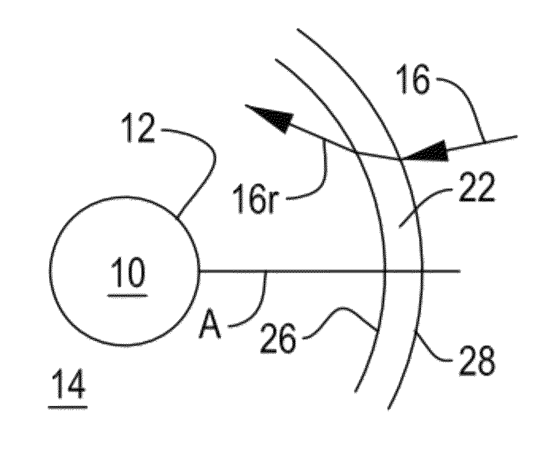
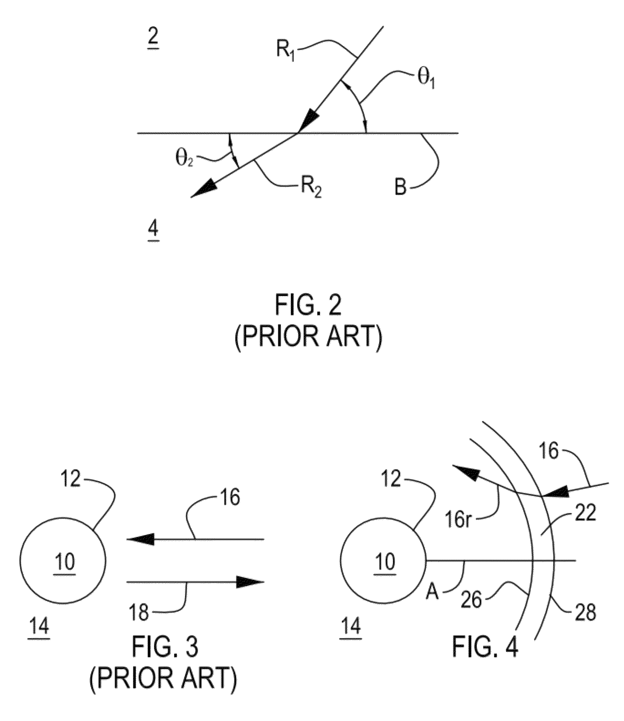
[0033]As illustrated in FIG. 4, there is shown an object 10 having a surface 12 positioned in the underwater environment 14. A device for producing an acoustic cloak 22 is provided proximate to the object 10 in the path of incident or incoming acoustic rays 16. The cloak 22 deflects incident rays 16 away from the object 10. The cloak 22 is defined as a relatively narrow band of seawater proximate to the object 10 having acoustic properties or characteristics sufficient to cause localized bending of the sound rays away from the object 10. In the exemplary arrangement, the object 10 has a central axis A and the cloak 22 is disposed proximate to the object 10 along the axis and conformal with the surface of the object 10 as shown.

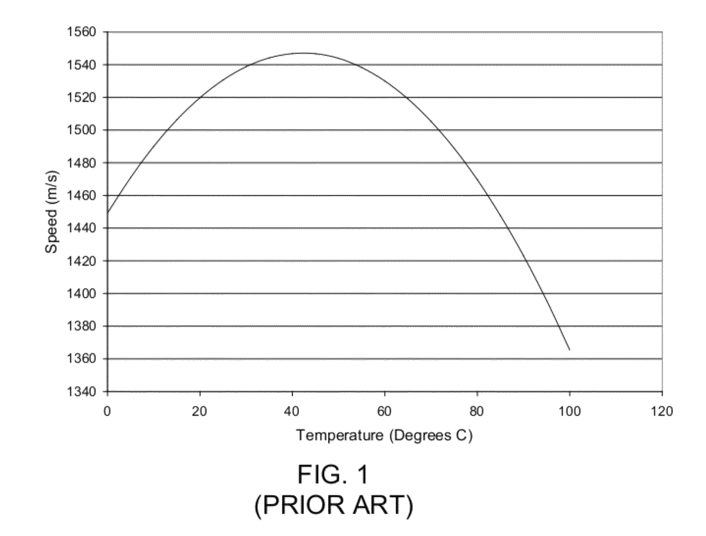
[0034]As noted above, the speed of sound c in a fluid, e.g., seawater, is variously affected by a number of parameters including temperature T and salinity. In accordance with an exemplary embodiment of the invention, a selected region of the fluid is heated o...


PUM


Abstract

A device for deflecting acoustic waves for an object in a liquid environment includes a heating grid and a cooling grid. The heating grid is positioned about the object and increases the temperature in the liquid environment. The cooling grid is positioned about the object to cool the liquid environment outside the heating grid. Jointly, these grids establish a temperature gradient in the liquid environment that is capable of bending acoustic waves in the environment. The cooling grid and heating grid can be established through mechanical, electrical or chemical methods. Alternatively, the required temperature gradient can be established by a heating grid alone in a moving vehicle wherein the heating grid is continuously in contact with undisturbed water at the ambient temperature.

Description

STATEMENT OF GOVERNMENT INTEREST[0001]The invention described herein may be manufactured and used by or for the Government of the United States of America for Governmental purposes without the payment of any royalties thereon or therefor.CROSS REFERENCE TO OTHER PATENT APPLICATIONS[0002]None.BACKGROUND OF THE INVENTION[0003](1) Field of the Invention[0004]The present invention is directed to a device for reducing target strength of an object submerged in a fluid. According to the invention, the device produces a region in the fluid exhibiting a high temperature gradient that induces localized bending of sound rays directed at the object away from the object to thereby effectively cloak it from acoustic detection.[0005](2) Description of the Prior Art[0006]An acoustic cloaking device generally has two main characteristics: (1) it does not generate significant acoustically sensible reflections, and (2) it bends sound rays directed toward the object sufficiently so that the rays avoid ...

Claims


Application Information

Patent Timeline
IPC IPC(8): H04K3/00
CPCH04K3/68G01S7/537H04K2203/12B63G8/36B63G8/42F41H3/00
Inventor RUFFA, ANTHONY A.GRIFFIN, JOHN F.
Owner THE UNITED STATES OF AMERICA AS REPRESENTED BY THE SECRETARY OF THE NAVY
Why Eureka
Try Eureka