Power control loop using a tunable antenna matching circuit

a power control loop and antenna matching technology, applied in power management, wireless communication, modulation, etc., can solve the problems of reducing the delivered power of the antenna, affecting the operation of the power supply system, so as to avoid interactions and instabilities, and avoid the disruption of the rf output signal.

Active Publication Date: 2012-11-27
QORVO US INC
View PDF6 Cites 145 Cited by
  • Summary
  • Abstract
  • Description
  • Claims
  • Application Information

AI Technical Summary

Benefits of technology

[0009]Prior art systems may use two separate control loops. A first control loop may be used for tunable antenna matching circuit adjustments and a second control loop may be used for RF power amplifier output power adjustments of a first RF terminal in response to output power adjustment commands received from a second RF terminal. However, interactions between the two separate control loops may cause instabilities. In one embodiment of the present disclosure, by bringing the tunable antenna matching circuit adjustments into the second control loop, such interactions and instabilities may be avoided.
[0010]In certain third generation (3G) and fourth generation (4G) communications protocols, full duplex operation is used. In full duplex operation, transmissions may be continuous. Therefore, in one embodiment of the present disclosure, the tunable antenna matching circuit adjustments and the RF power amplifier output power adjustments may be made at slot boundaries of an RF output signal to provide stability and avoid disruption of the RF output signal.

Problems solved by technology

Impedance mismatches may cause reflections of the RF output signal, thereby reducing the delivered power to the antenna.
As a result, providing a matched impedance to the antenna under all operating conditions may be problematic.
Holding a cell phone next to a user's body or laying the cell phone on a table may change the input impedance, thereby causing impedance mismatches.
Experimental data has shown that normal body movements can cause significant antenna input impedance changes in time frames on the order of one millisecond.
As such, adjustments made to the tunable antenna matching circuit may influence or cause errors to the output power adjustments of the first RF terminal in response to commands from the second RF terminal.

Method used


Image

  • Power control loop using a tunable antenna matching circuit
  • Power control loop using a tunable antenna matching circuit
  • Power control loop using a tunable antenna matching circuit

Examples


Embodiment Construction

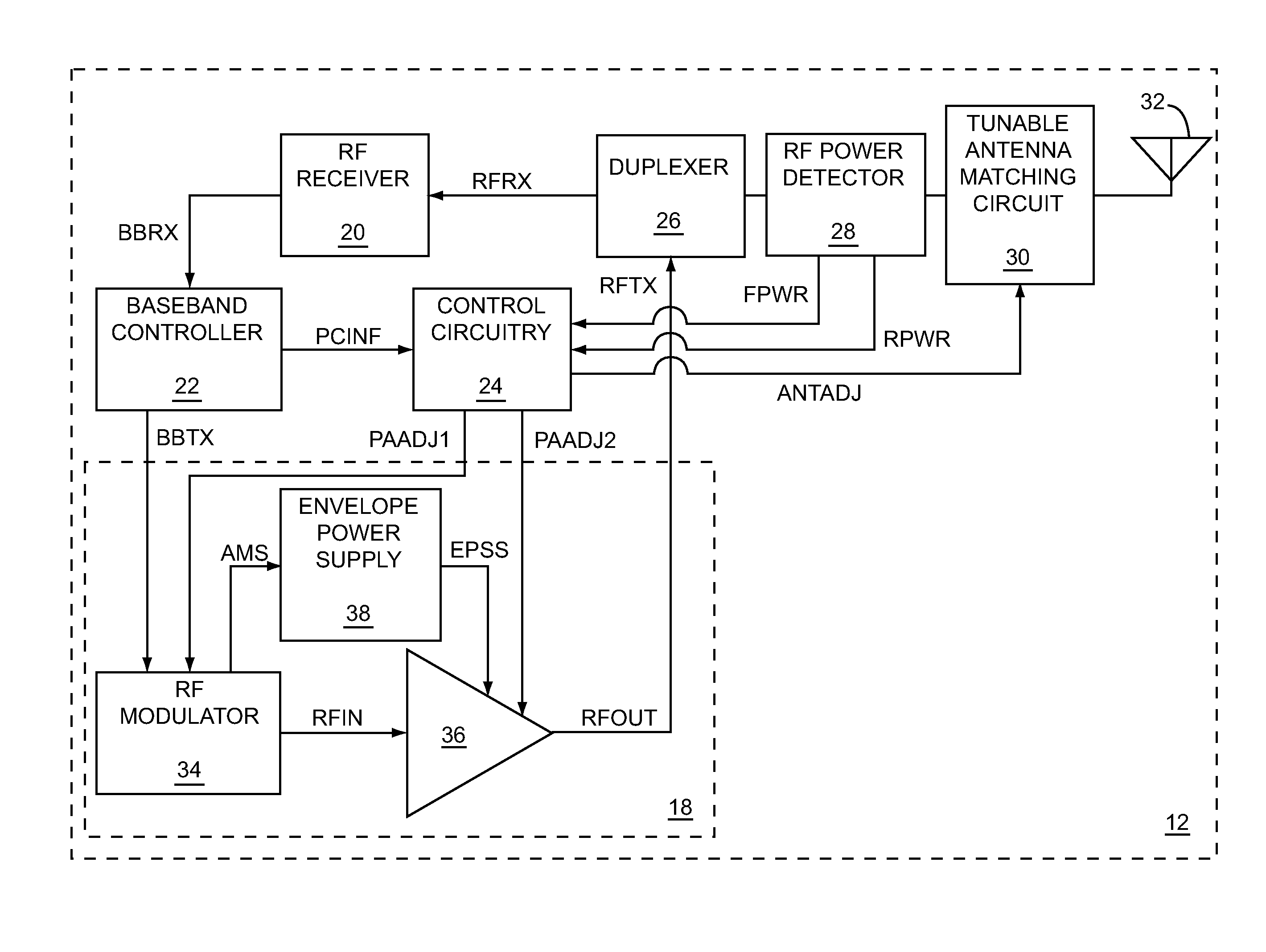
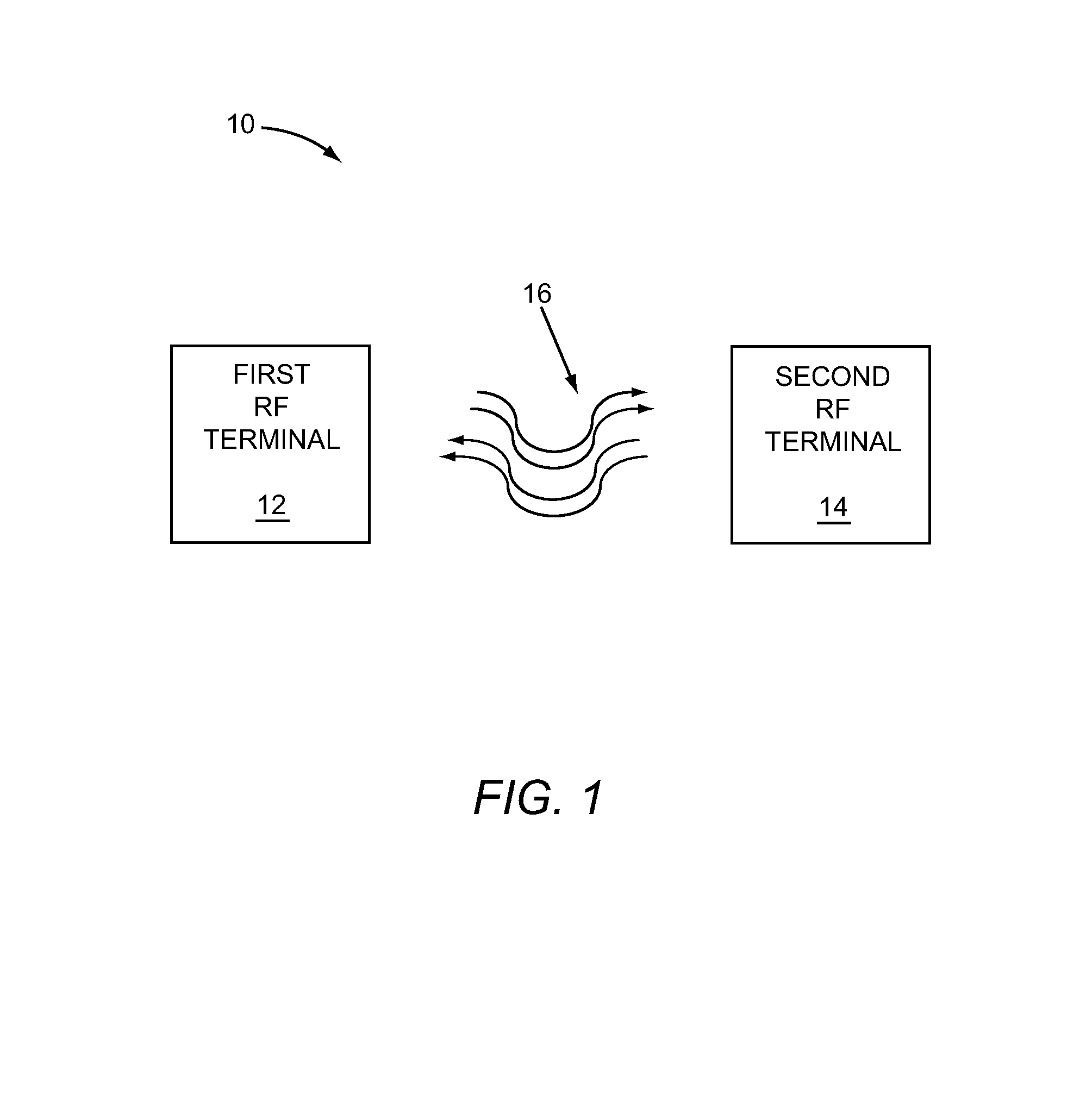
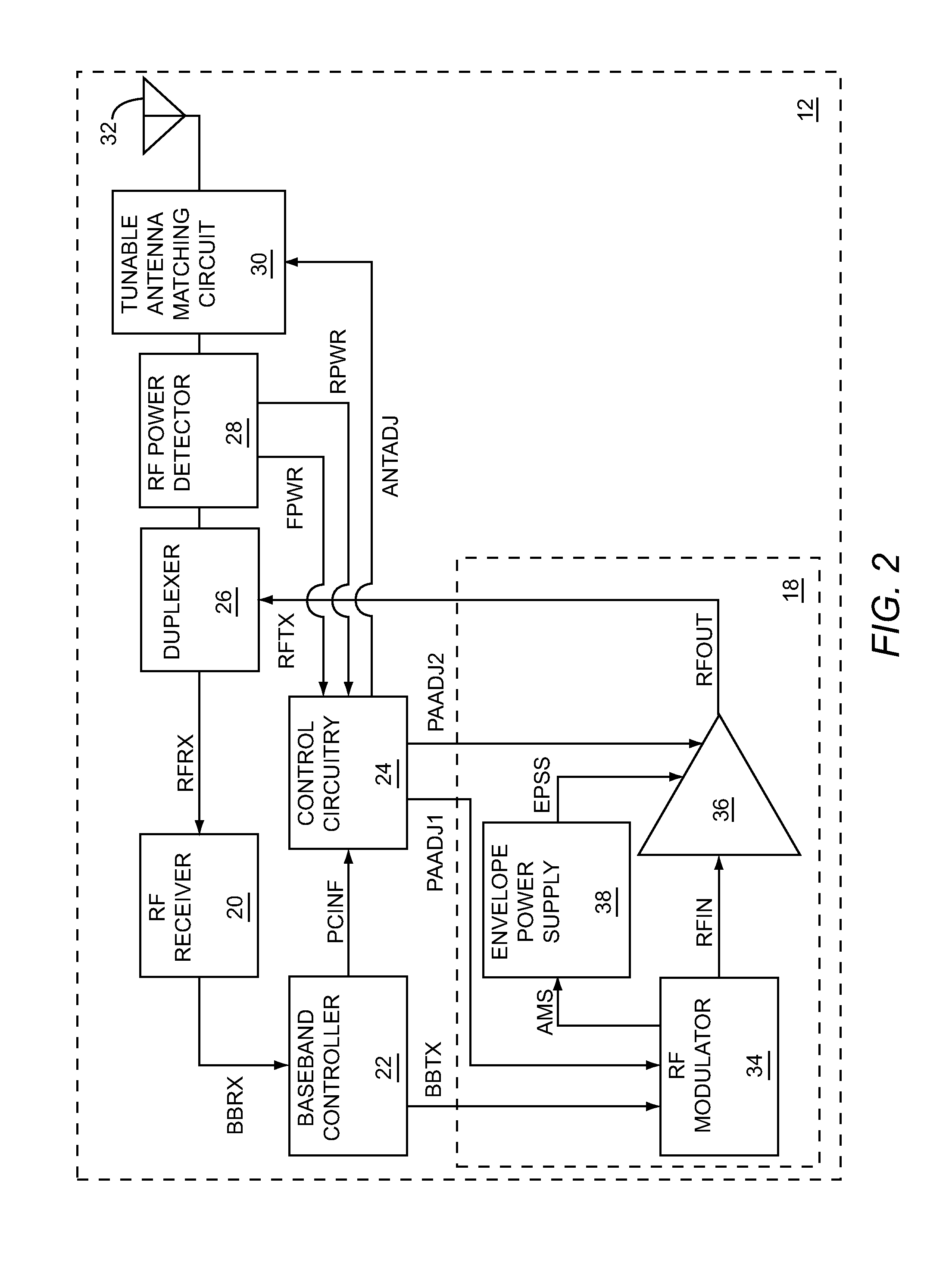
[0007]The present disclosure relates to combining tunable antenna matching circuit adjustments and RF power amplifier output power adjustments of a first RF terminal in response to output power adjustment commands received from a second RF terminal. The output power adjustment commands may be part of an output power control loop between the first RF terminal and the second RF terminal to control the output power from the first RF terminal. The first RF terminal may include an RF receiver, an RF power amplifier, and a tunable antenna matching circuit coupled between an output of the RF power amplifier and an antenna. The output power adjustment commands are received by the RF receiver and the tunable antenna matching circuit adjustments may be impedance adjustments of the tunable antenna matching circuit. The RF power amplifier output power adjustments may result from adjustments to one or more input signals to the RF power amplifier.

[0008]For example, the RF power amplifier output p...


PUM


Abstract

The present disclosure relates to combining tunable antenna matching circuit adjustments and RF power amplifier output power adjustments of a first RF terminal in response to output power adjustment commands received from a second RF terminal. The output power adjustment commands may be part of an output power control loop between the first RF terminal and the second RF terminal to control the output power from the first RF terminal. The first RF terminal may include an RF receiver, an RF power amplifier, and a tunable antenna matching circuit coupled between an output of the RF power amplifier and an antenna. The tunable antenna matching circuit adjustments may be impedance adjustments of the tunable antenna matching circuit and the RF power amplifier output power adjustments may result from adjustments to one or more input signals to the RF power amplifier.

Description

[0001]This application claims the benefit of provisional patent application Ser. No. 61 / 161,333, filed Mar. 18, 2009 the disclosure of which is hereby incorporated herein by reference in its entirety.FIELD OF THE DISCLOSURE[0002]Embodiments of the present disclosure relate to tunable antenna matching circuits and radio frequency (RF) transceivers that may be used in RF communications systems.BACKGROUND OF THE DISCLOSURE[0003]In an RF communications system, an RF power amplifier feeds an RF output signal to an antenna for transmission. The delivered power to the antenna may be affected by an impedance match between the RF power amplifier and the antenna. Impedance mismatches may cause reflections of the RF output signal, thereby reducing the delivered power to the antenna. There are several possible causes of impedance mismatch. In a multi-mode or multi-band RF system, the antenna may need to be coupled to multiple RF power amplifiers, to multiple RF receivers, or the like. As a resu...

Claims


Application Information

Patent Timeline
Patent Type & Authority Patents(United States)
IPC IPC(8): H03C1/52H01Q11/12H04B1/04
CPCH03H7/40H04W52/52
Inventor KHLAT, NADIM
Owner QORVO US INC
Why Eureka
Try Eureka