Heat dissipation device with pivotable fan

a technology of heat dissipation device and fan, which is applied in the direction of electrical apparatus casing/cabinet/drawer, semiconductor/solid-state device details, instruments, etc., can solve the problems of adversely increasing the cost of heat dissipation, one type heat dissipation device can only produce one type of airflow,

Inactive Publication Date: 2012-12-04
HONG FU JIN PRECISION IND (SHENZHEN) CO LTD +1
View PDF14 Cites 7 Cited by
  • Summary
  • Abstract
  • Description
  • Claims
  • Application Information

AI Technical Summary

Benefits of technology

[0004]With the fast development of electronic industry, advanced electronic components such as CPUs (central processing units), or GPUs (graphics processing units) are being made with ever faster operating speeds. Greater emphasis is now being laid on increasing the efficiency and effectiveness of heat dissipation devices so as to keep operational temperature of the electronic components within a suitable range. Generally, in order to ensure a temperature of a heat-generating electronic component within a safe threshold level, a heat dissipation device is provided, which comprises a heat sink and a fan combined to the heat sink. The fan is fixed to the heat sink at a predetermined position of a top or a lateral side of the heat sink by a fan holder.

Problems solved by technology

However, such fixed relation of the fan to the heat sink causes the heat dissipation device to be used in a limited way.
That is, one type heat dissipation device can only produce one type airflow (for example, the heat sink with the fan fixed on the top of thereof can only have a downward airflow, and the heat sink with the fan fixed on the lateral thereof can only have a lateral-ward airflow).
Thus, when the environment of the heat dissipation device is changed, the heat dissipation device also has to be replaced by a different one in order to produce the right airflow suitable for the changed environment, which adversely increases the cost of heat dissipation.

Method used


Image

  • Heat dissipation device with pivotable fan
  • Heat dissipation device with pivotable fan
  • Heat dissipation device with pivotable fan

Examples


Embodiment Construction

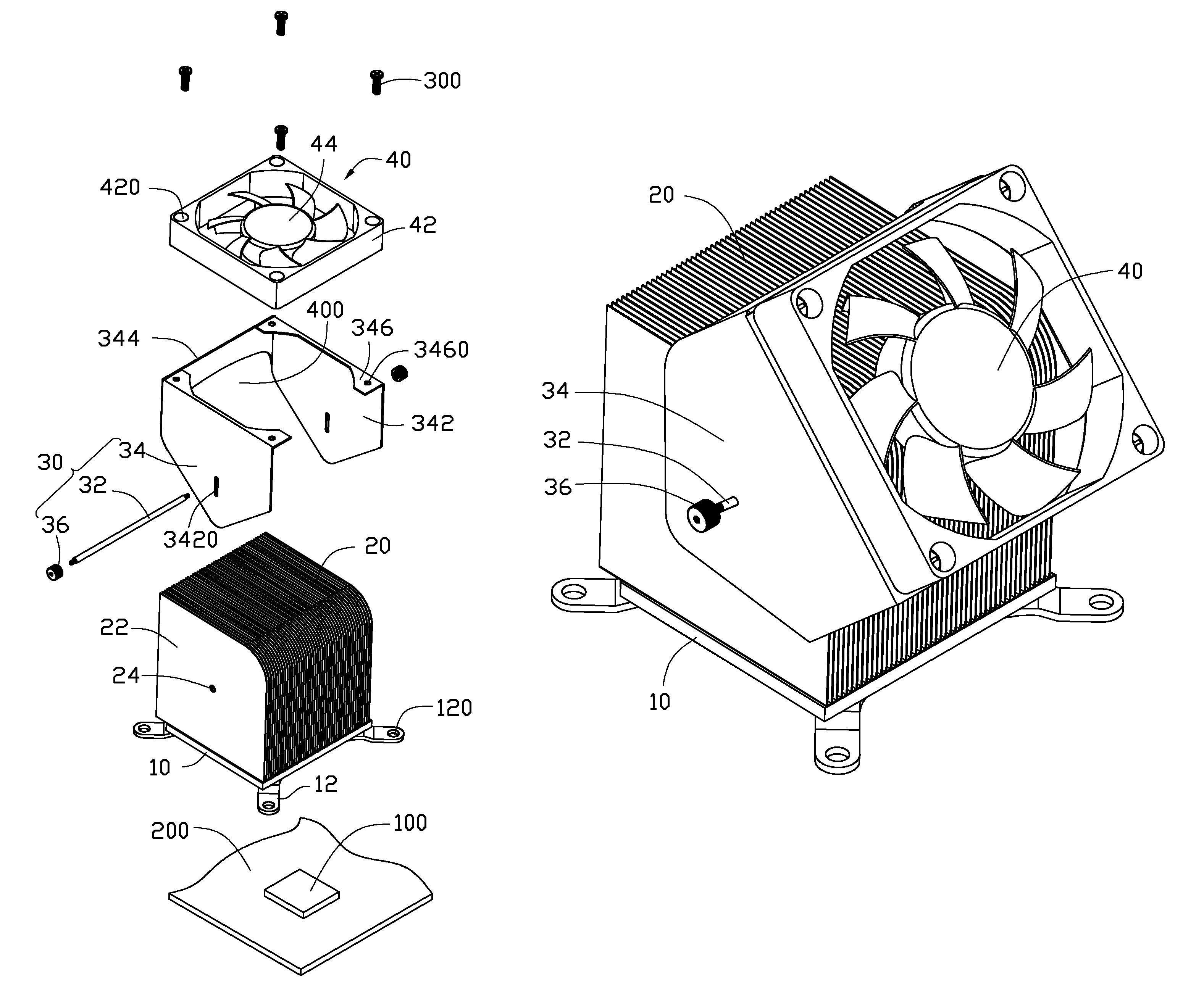
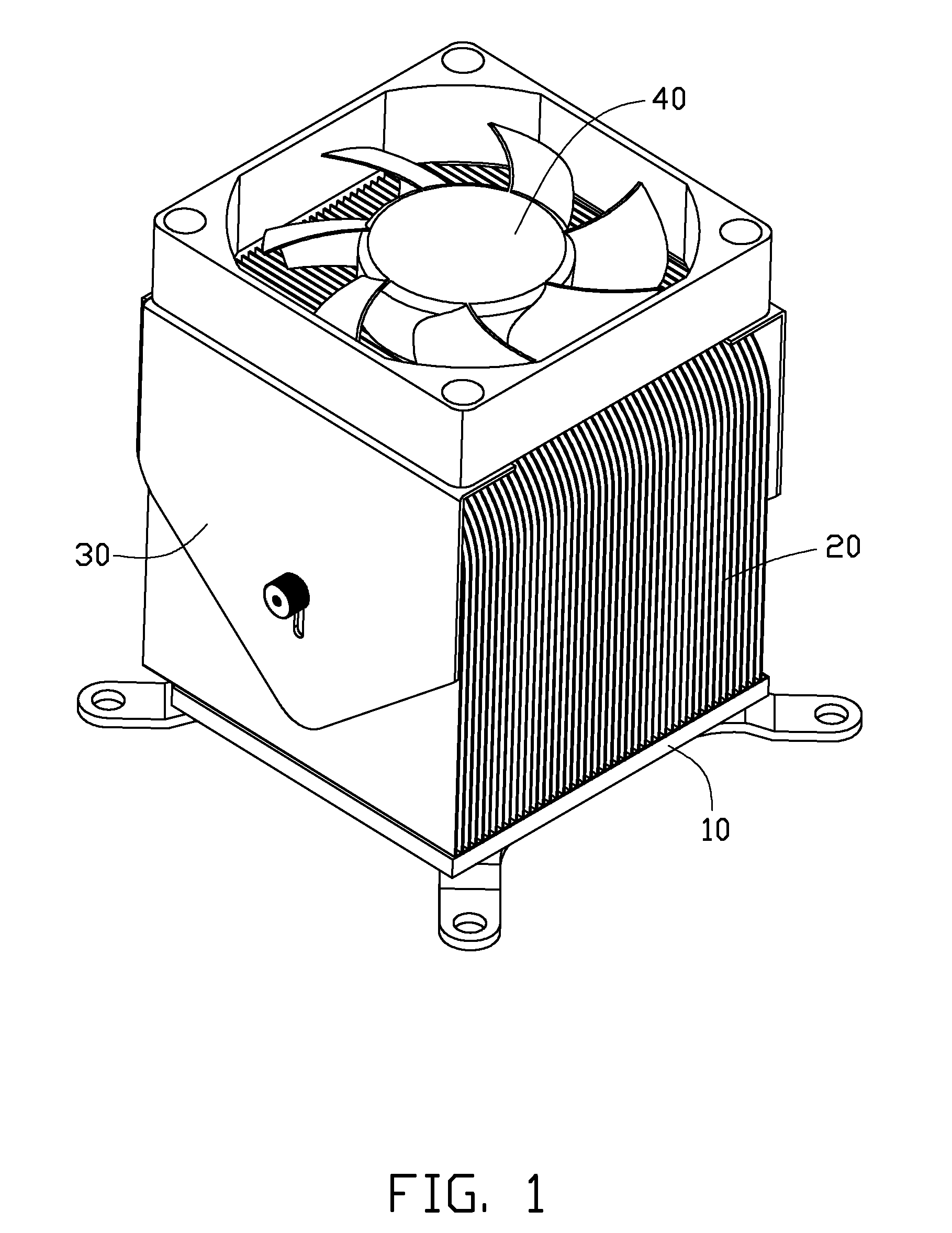
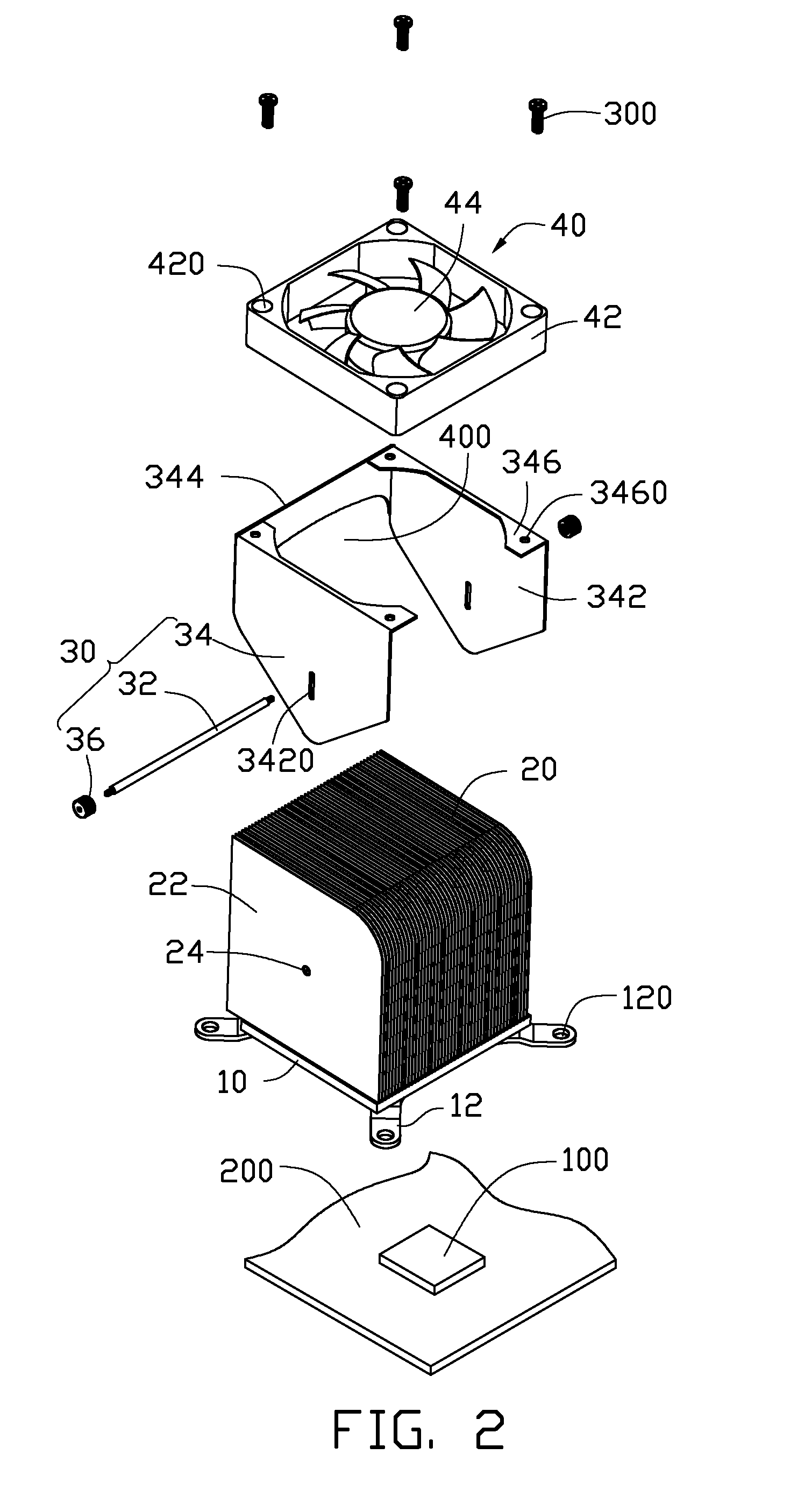
[0012]Referring to FIGS. 1-2, a heat dissipation device in accordance with an embodiment of the disclosure is illustrated. The heat dissipation device dissipates heat from an electronic component 100 such as a CPU (central processing unit), which is mounted on a printed circuit board 200. The heat dissipation device comprises a heat conducting board 10 attached to the electronic component 100, a fin unit 20 disposed on the heat conducting board 10, a fixing module 30 disposed on the heat conducting board 10, and a fan 40 secured on the fixing module 30 to produce an airflow through the fin unit 20.

[0013]The heat conducting board 10 is integrally formed of a metallic material with a good thermal conductivity, such as copper, aluminum or an alloy thereof. A bottom face of the heat conducting board 10 is attached to the electronic component 100. Four arms 12 extend outwardly from four corners of the heat conducting board 10, respectively. Each arm 12 defines a through hole 120 at a fre...


PUM


Abstract

A heat dissipation device includes a heat conducting board attached to an electronic component mounted on a printed circuit board, a fin unit disposed on the heat conducting board, a fixing module, and a fan secured on the fixing module. The fixing module includes a pivoting post extending through the fin unit, a fan holder spanning over the fin unit and pivotally fixed to the pivoting post, and two fastening members engaging with two opposite ends of the pivoting post and being capable of fixing the fan holder at different positions relative to the fin unit. The fan is fixed to the fan holder of the fixing module and provides airflow towards the fin unit.

Description

BACKGROUND[0001]1. Technical Field[0002]The disclosure generally relates to heat dissipation devices and, more particularly, to a heat dissipation device incorporating a fan.[0003]2. Description of Related Art[0004]With the fast development of electronic industry, advanced electronic components such as CPUs (central processing units), or GPUs (graphics processing units) are being made with ever faster operating speeds. Greater emphasis is now being laid on increasing the efficiency and effectiveness of heat dissipation devices so as to keep operational temperature of the electronic components within a suitable range. Generally, in order to ensure a temperature of a heat-generating electronic component within a safe threshold level, a heat dissipation device is provided, which comprises a heat sink and a fan combined to the heat sink. The fan is fixed to the heat sink at a predetermined position of a top or a lateral side of the heat sink by a fan holder.[0005]However, such fixed rel...

Claims


Application Information

Patent Timeline
Patent Type & Authority Patents(United States)
IPC IPC(8): F28F7/00H05K7/00H05K7/20
CPCH01L23/467H01L23/4006H01L2023/4056H01L2023/4062H01L2924/0002H01L2023/4087H01L2924/00
Inventor TANG, XIAN-XIUYE, ZHEN-XING
Owner HONG FU JIN PRECISION IND (SHENZHEN) CO LTD
Why Eureka
Try Eureka