Integrated optical sensor

a sensor and optical sensor technology, applied in the field of integrated optical sensors, can solve the problems of increasing the cost and the required measuring time, the difficulty of offering the sensor platform in a micro-titer plate format, and the primary sensitivity of the sensor, so as to achieve high and adjustable sensitivity, low cost per measuring point, and high readout speed

Active Publication Date: 2012-12-04
CREOPTIX
View PDF10 Cites 8 Cited by
  • Summary
  • Abstract
  • Description
  • Claims
  • Application Information

AI Technical Summary

Benefits of technology

[0008]It is therefore the objective of the invention to create a sensor unit which can be used in particular for (bio-) chemical measurements of the type mentioned at the outset, which provides a high and adjustable sensitivity, a high readout speed, low costs per measuring point, and a large measuring range, and is suitable for integration into micro titer plates.

Problems solved by technology

A disadvantage of SPR sensors—especially of those based on prism couplers—is the difficulty to offer sensor platforms in a micro titer plate format.
Furthermore, the measuring method is inherently sensitive to manufacturing tolerances since it is based on a resonance depending on the (angular) position of the sensor platform, therefore small tolerances must be used and complex calibrations must be carried out, which increases the costs as well as the required measuring time.
Another disadvantage consists in the fact that the primary sensitivity of the sensor (the dependence of the measured physical value like angle or wavelength on the parameter to be measured such as adsorption of the molecules) mainly depends on the material of the waveguide and can hardly be influenced by design measures.
As is the case for SPR sensors, the measuring method is based on an optical resonance, and has the disadvantage of the sensitivity to manufacturing tolerances.
Besides, the measurement range is limited by the scanning range of the measured variables such as angle or wavelength, and fast readout speeds could only be shown within a limited measuring range.
A disadvantage of this method—even more than in the previous examples and as is described in the patent—is the calibration step required before starting a measurement and the costs associated to it.
Although the described measurement method shows a large measurement range, it can not or only hardly be integrated into a platform having several measuring points, because the readout of the interferometric signal occurs in a plane situated perpendicular to the waveguide.
Furthermore, the manufacture of the sensor platforms as well as the instrument is very cost-intensive, and the extraction of a useful signal from the interference patterns is complex.

Method used


Image

  • Integrated optical sensor
  • Integrated optical sensor
  • Integrated optical sensor

Examples


Embodiment Construction

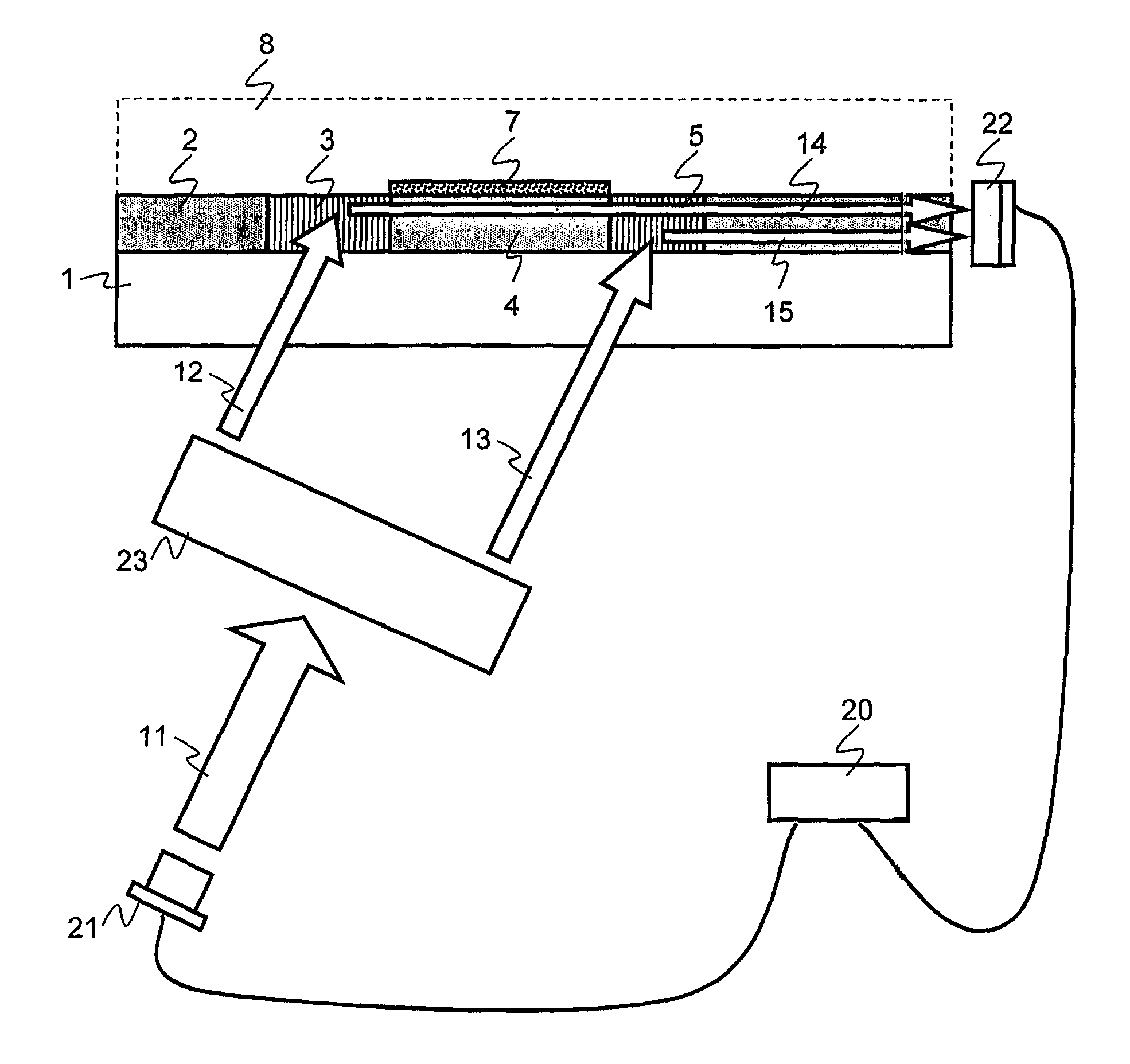
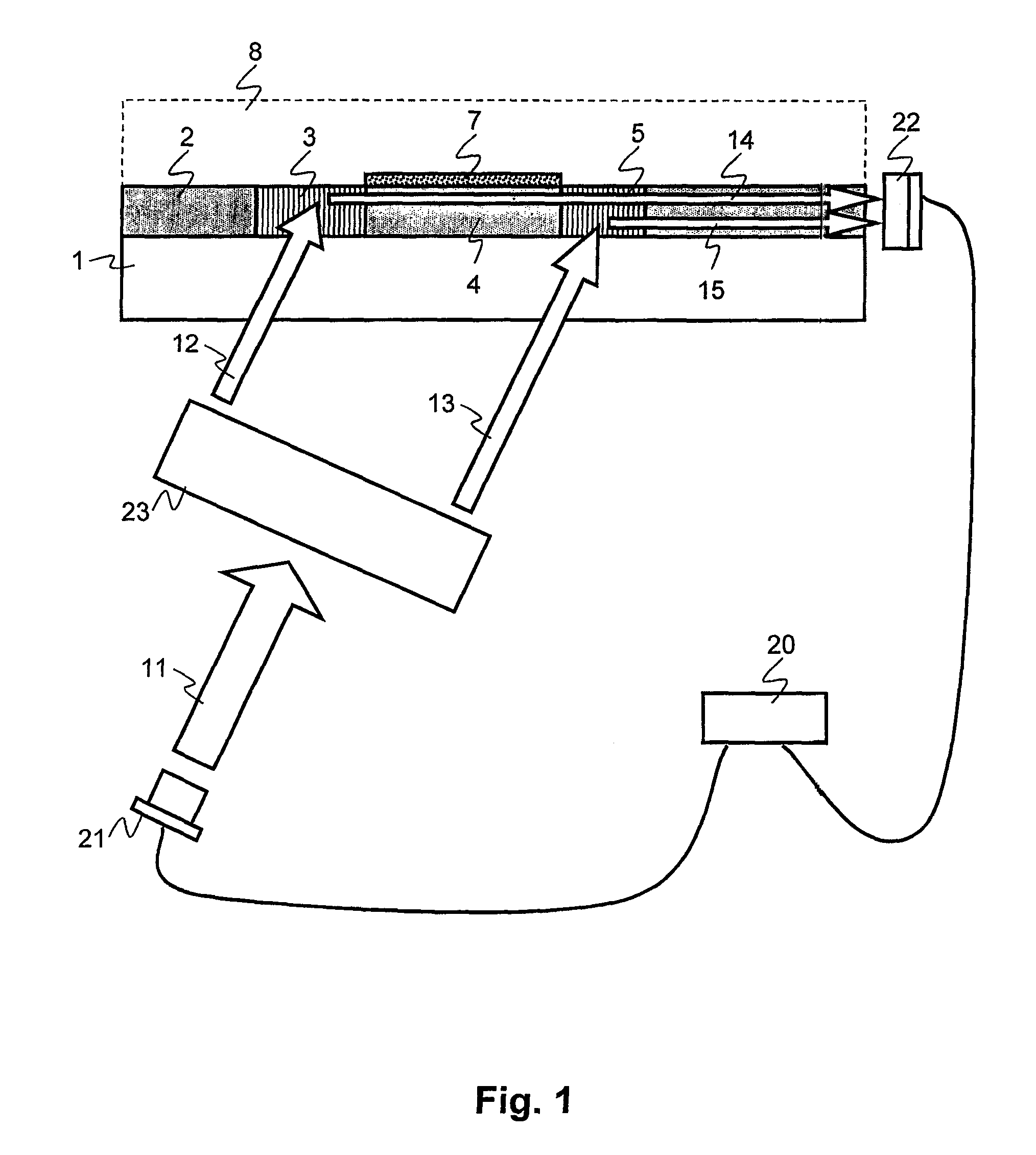
[0046]FIG. 1 illustrates a cross section of a sensor and corresponding light paths. The sensor comprises a light source (21), which irradiates illumination optics (23). The light source (21) is preferably a diode laser with a wavelength from 400 nm to 800 nm, but preferably with a wavelength of 635 or 650 nm. The illumination optics (23) divide the beam into two parts, namely a sensing beam (12) and a reference beam (13) which are incident on incoupling regions (3, 5) of the waveguide (2) preferably through a substrate (1). The sensing beam (12) excites a sensing wave (14) in a waveguide (2) through a first incoupling region (3), the former subsequently traversing a sensing area (4). The sensing area (4) is provided with an additional layer (7) which can bind a (bio-) chemical substance from the analyte (8). The analyte (8) can be either a liquid or a gas. Through the second incoupling region (5) a reference wave (15) is excited in the waveguide (2) by the reference beam (13). The s...


PUM


Abstract

An integrated optical sensor for, for example, a (bio)chemical sensor has an optical waveguide (2) having at least two coupling regions (3, 5), which are separated by at least one measurement region (4). A first wave is excited in the waveguide (2) by the first coupling region (3) and passes through the measurement region (4) and the second coupling region (5). A second wave is excited in the second coupling region (5) and subsequently interferes with the first wave. Here, the reduction in amplitude of the first wave by the second coupling region (5) is less than 95%.

Description

[0001]The invention is related to the field of label-free optical sensors with high sensitivity, large measuring range, high readout speed and high robustness with respect to manufacturing tolerances, particularly consisting of integrated-optical waveguides and a readout device, and their application to (bio-) chemical sensor units, as they find use, for example, in pharmacology or in diagnostics.DESCRIPTION OF RELATED ART[0002]Label-free (bio-) chemical sensors based on optical readout schemes are generally known. Compared to widespread marker-based methods using for example fluorescent, absorbing or radioactive markers, these measurement methods have the advantage that the measuring process is not influenced by the presence of a marker. This is important for example for the observation of small molecule binding. Another advantage lies in the potential reduction of costs and time necessary for a measurement, since the marker preparation step is left out before the actual measuremen...

Claims


Application Information

Patent Timeline
Patent Type & Authority Patents(United States)
IPC IPC(8): G01B9/02
CPCG01N21/45G01N21/7703G01N2021/458G01N2021/7776
Inventor COTTIER, KASPAR
Owner CREOPTIX
Why Eureka
Try Eureka