
Integrated boiler component wiring assembly and method

a technology for wiring components and boilers, applied in lighting and heating apparatus, heating types, and semiconductor/solid-state device details, etc., can solve the problems of difficulty in learning to correctly connect lack of organization of the wires connecting the components, and the difficulty of wiring tasks for technicians to learn, so as to facilitate the electrical connection of components and reduce the amount of time , the effect of facilitating the diagnosis of problems with the components of the boiler heating system

Inactive Publication Date: 2012-12-04
HARPER JAMES T
View PDF22 Cites 4 Cited by
  • Summary
  • Abstract
  • Description
  • Claims
  • Application Information

AI Technical Summary

Benefits of technology

"The present invention is about an integrated boiler component wiring assembly that simplifies the process of connecting the components of a boiler heating system. This wiring assembly reduces the time required to wire the system, makes it easier to diagnose and repair problems, and reduces the cost of training technicians. It also reduces the need for service calls and the cost of electrical conductors. The wiring assembly has a housing with multiple internal conductors that connect the components of each zone. The method involves connecting the transformer, boiler start switch, thermostat, and zone valve using the integrated wiring assembly. Overall, this invention simplifies the process of connecting components and improves the efficiency and reliability of boiler heating systems."

Problems solved by technology

Properly connecting the end switches, the boiler start switch, the thermostats in each zone and the zone valves is typically one of the most difficult wiring tasks for a technician to learn.
One of the factors that contributes to the difficulty in learning to correctly connect the components of the boiler heating system is a lack of organization of the wires connecting the components.
Even experienced technicians can spend a significant amount of time determining the wiring configuration.
The time spent trying to determine which roles the connecting wires in a boiler heating system play adds extra cost to service calls.
The cost to install a typical boiler heating system is also more expensive due to the lack of organization and clear identification of the electrical conductors which connect the boiler heating system components.

Method used


Image

  • Integrated boiler component wiring assembly and method
  • Integrated boiler component wiring assembly and method
  • Integrated boiler component wiring assembly and method

Examples


Embodiment Construction

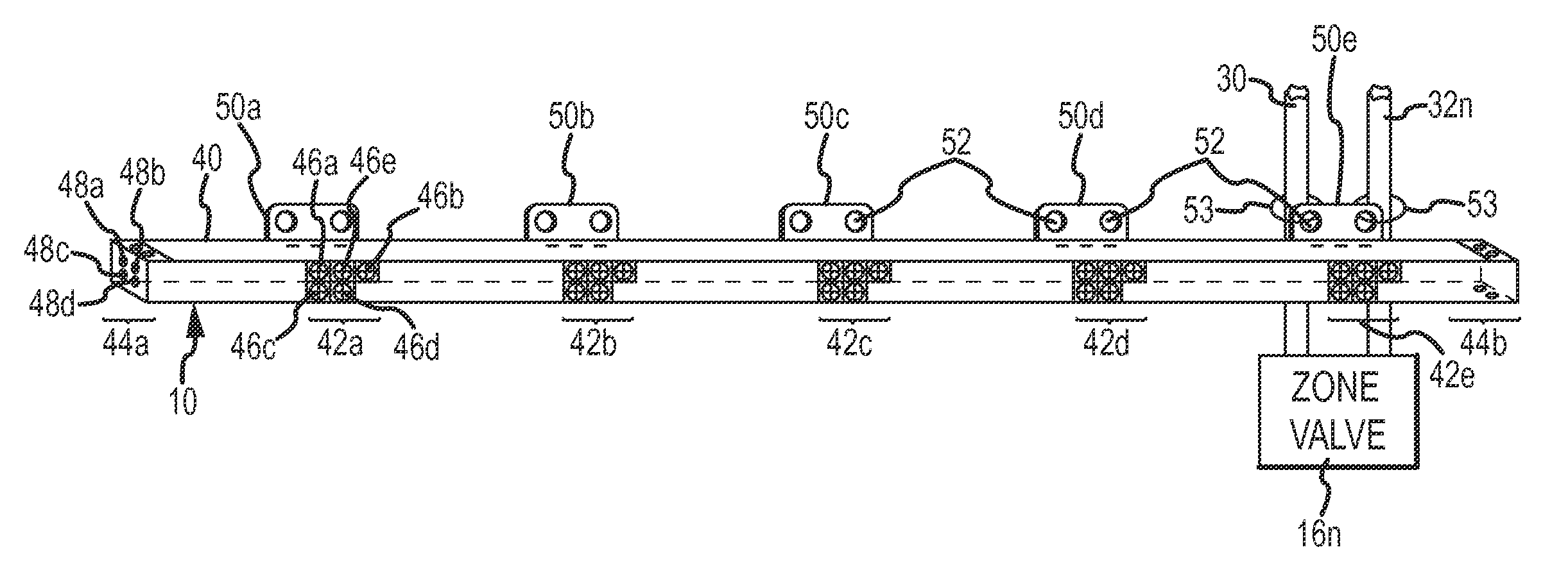
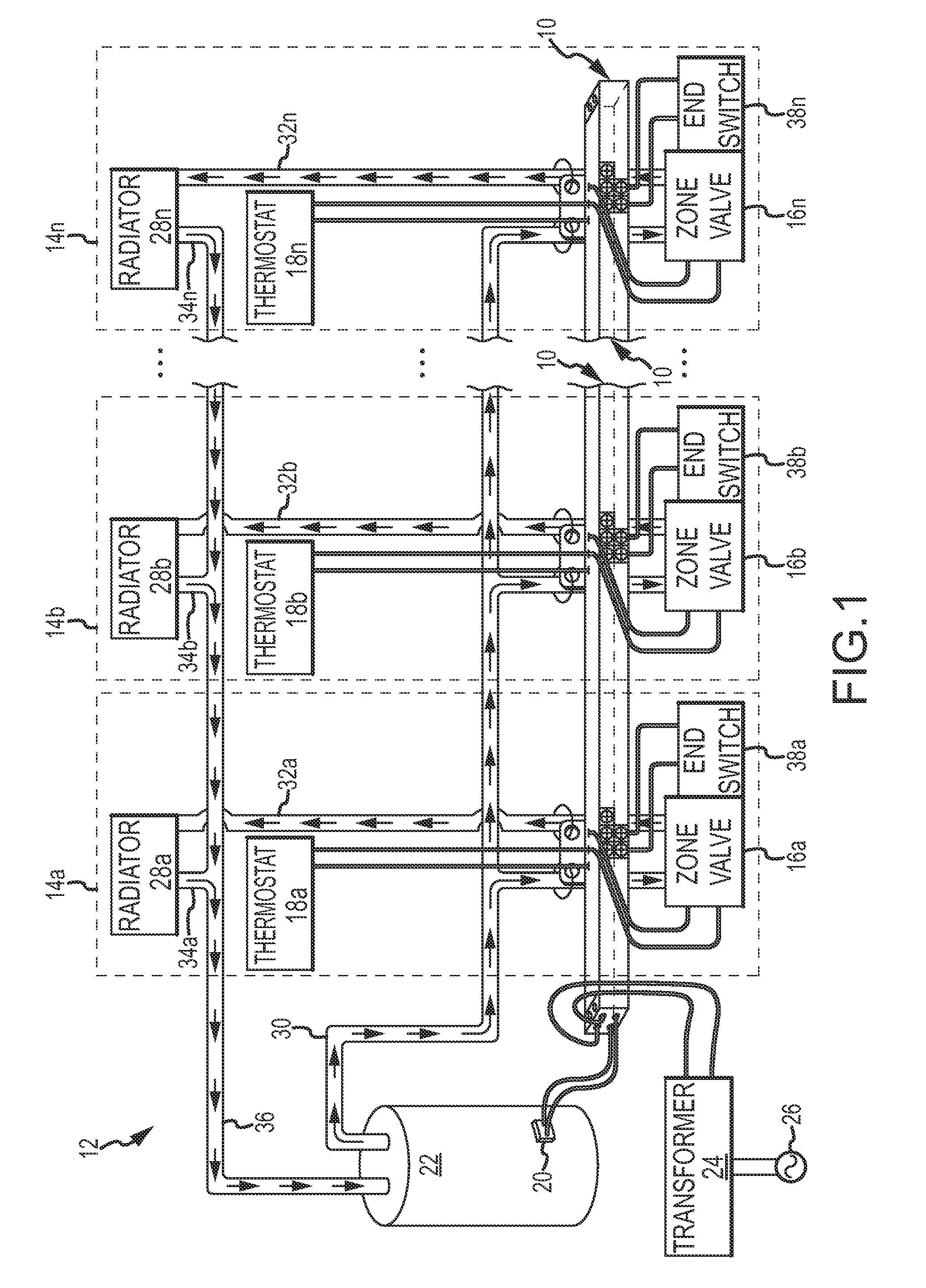
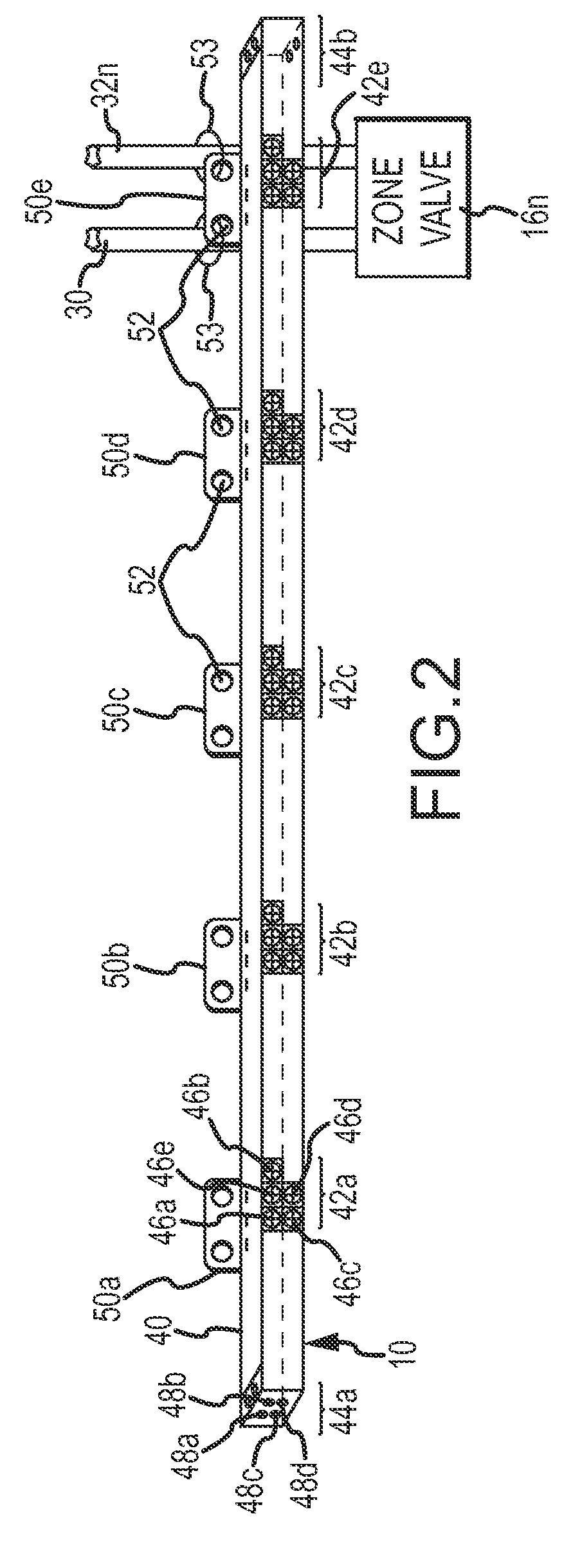
[0017]An integrated wiring assembly 10 which embodies the present invention is shown in FIG. 1. The integrated wiring assembly 10 electrically connects various components of a boiler heating system 12 within a plurality of different zones 14a-14n of a residential or commercial building (not shown). The boiler components of the heating system 12 include zone valves 16a-16n and thermostats 18a-18n, one of each of which is associated with each zone 14a-14n, and a start switch 20 of a boiler 22 and a transformer 24. The integrated wiring assembly 10 connects these components within each of the zones 14a-14n and in the boiler system 12 as a whole. The transformer 24 supplies electrical power from commercially available electrical power 26 to the integrated wiring assembly 10. The integrated wiring assembly 10 distributes the electrical power to the zone valves 16a-16n and thermostats 18a-18n to cause those components to function independently with respect to each zone 14a-14n, respective...


PUM


Abstract

An integrated wiring assembly electrically connects components of a multi-zone boiler heating system. The integrated wiring assembly includes a plurality of connection terminals which are commonly connected to facilitate connecting thermostats and zone valves for each zone, end switches of each zone valve to a start switch of the boiler, and a transformer to supply electrical power to the components, in such a way that the complexity of the electrical connections is simplified.

Description

[0001]This invention relates to electrically connecting together various components of a boiler heating system. More particularly, the present invention relates to a new and improved integrated wiring assembly and method which greatly facilitates electrically connecting the components of the boiler heating system and which aids in more quickly diagnosing problems associated with the components of the boiler heating system.BACKGROUND OF THE INVENTION[0002]Boiler heating systems are widely used to heat residential and commercial buildings. A typical boiler heating system includes a boiler, pipes, radiators and water or similar heat transfer fluid. The boiler generates heat from a heat source, such as a resistive heating element or a combustion chamber in which fuel is burned. The heat is transferred to the water, and the heated water is then pumped through supply pipes to radiators located within the interior of a building. Heat from the heated water flowing through the radiators is t...

Claims


Application Information

Patent Timeline
Patent Type & Authority Patents(United States)
IPC IPC(8): H05B3/60A21D6/00
CPCF24D11/004F24D19/1006F24D19/1009
Inventor HARPER, JAMES T.
Owner HARPER JAMES T
Learn More