
Exhaust system comprising catalysed soot filter

a technology of catalytic soot and exhaust system, which is applied in the direction of machine/engine, electrical control, exhaust treatment, etc., can solve the problems of unfavorable direct measurement of inlet gas conditions. , to achieve the effect of increasing the temperature of the cs

Active Publication Date: 2012-12-11
JOHNSON MATTHEY PLC
View PDF37 Cites 6 Cited by
  • Summary
  • Abstract
  • Description
  • Claims
  • Application Information

AI Technical Summary

Benefits of technology

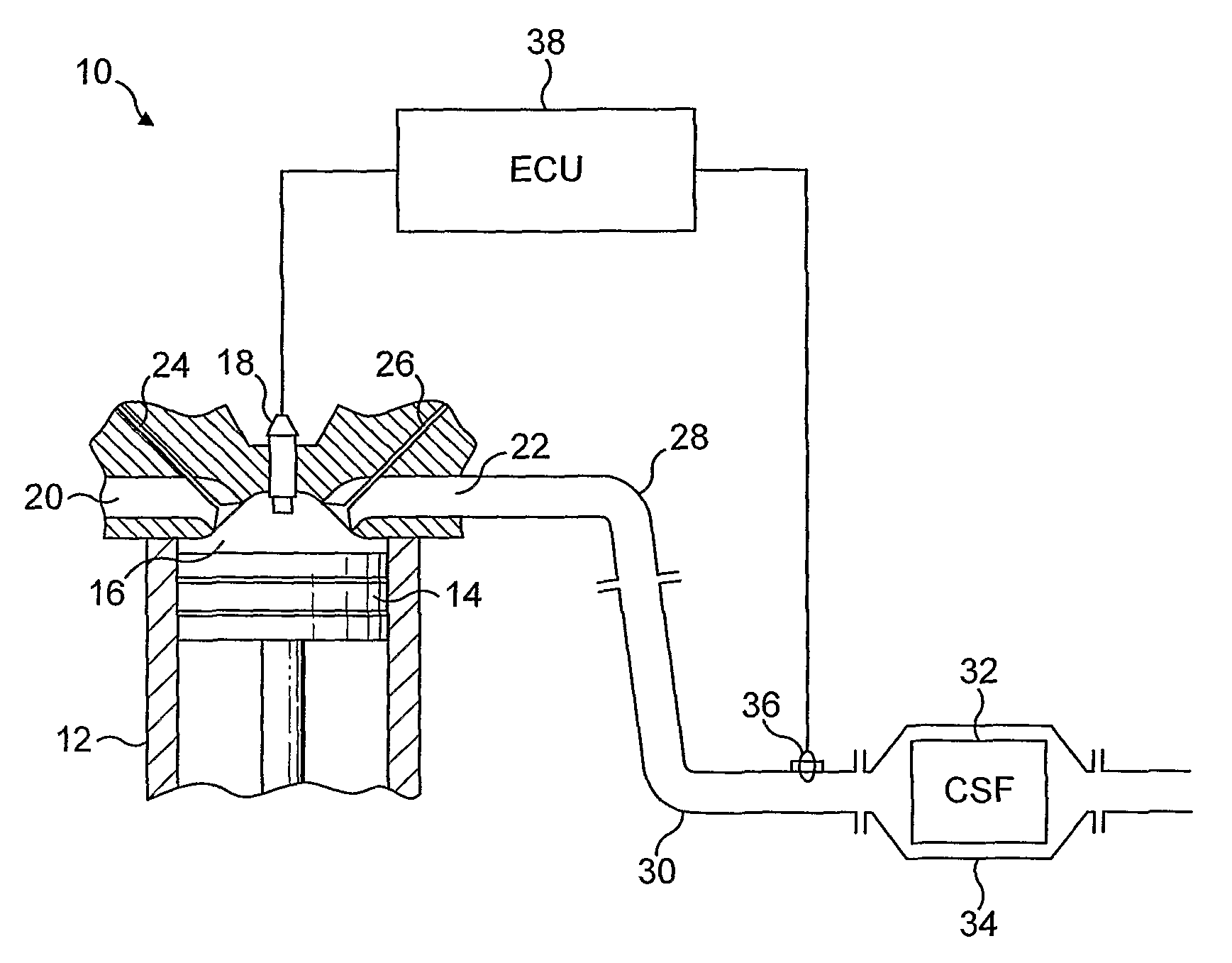
The invention is an exhaust system for a lean burn internal combustion engine that includes a catalysed soot filter (CSF), a control unit, and means for increasing the content of combustible HC and / or CO in the exhaust gas flowing into the CSF. This system also includes a catalysed sensor means for combusting CO and / or HC in exhaust gas flowing in the exhaust system and inputting the control unit with a datum correlating with the enthalpy of combustion of HC and / or CO in the exhaust gas. The control unit, in response to the datum input, controls the combustible HC and / or CO introducing means to control the rate of contacting the CSF with combustible HC and / or CO. The technical effect of this invention is to increase the temperature of the CSF and to combust PM collected thereon, thereby improving the engine's efficiency and reducing emissions.

Problems solved by technology

A known problem with using CSFs is that PM can build up on the CSF during periods when the exhaust gas temperature is relatively cool, e.g. 150-200° C., such as during extensive periods of idling and / or in slow driving conditions.
In such circumstances, backpressure in the system can rise undesirably as PM collects on the CSF.
However, there remains the problem of accurately controlling the energy input to the CSF in order to avoid exposing the catalyst coating and filter substrate to damagingly high temperatures, e.g. >650° C., but ensuring that sufficient energy is introduced to the CSF to combust PM thereon.
Firstly, additional heat from combustion of PM cannot be differentiated from heat derived from combusting HC and / or CO from the exhaust gas thus rendering direct measurement of the inlet gas conditions difficult or practically impossible.
Secondly, there are durability problems associated with placing a small diameter thermocouple within the cell structure of the CSF: the thermocouple or filter can be damaged.

Method used


Image

  • Exhaust system comprising catalysed soot filter
  • Exhaust system comprising catalysed soot filter

Examples


first embodiment

[0022]In a further embodiment, the catalysed sensor means comprises the catalysed thermocouple junction of the first embodiment and additionally an uncatalysed reference thermocouple junction. Such a sensor is described in U.S. Pat. No. 4,029,472, the entire contents of which is incorporated herein by reference. This arrangement of two thermocouple junctions provides the advantage that the sensor is able to determine the heat derived from combustion of HC and / or CO on the CSF as well as the pre-CSF exhaust gas temperature so that additional feedback control can be provided to the control unit.

[0023]The catalyst in the CSF typically comprises at least one platinum group metal (PGM), but in particular embodiments it comprises Pt either alone or in combination with one or more additional PGM, such as both Pt and Pd or both Pt and Rh or all three of Pt, Pd and Rh including suitable promoters such as Mg, Ba or rare earth metals such as Ce. The material from which filter substrate monolit...

second embodiment

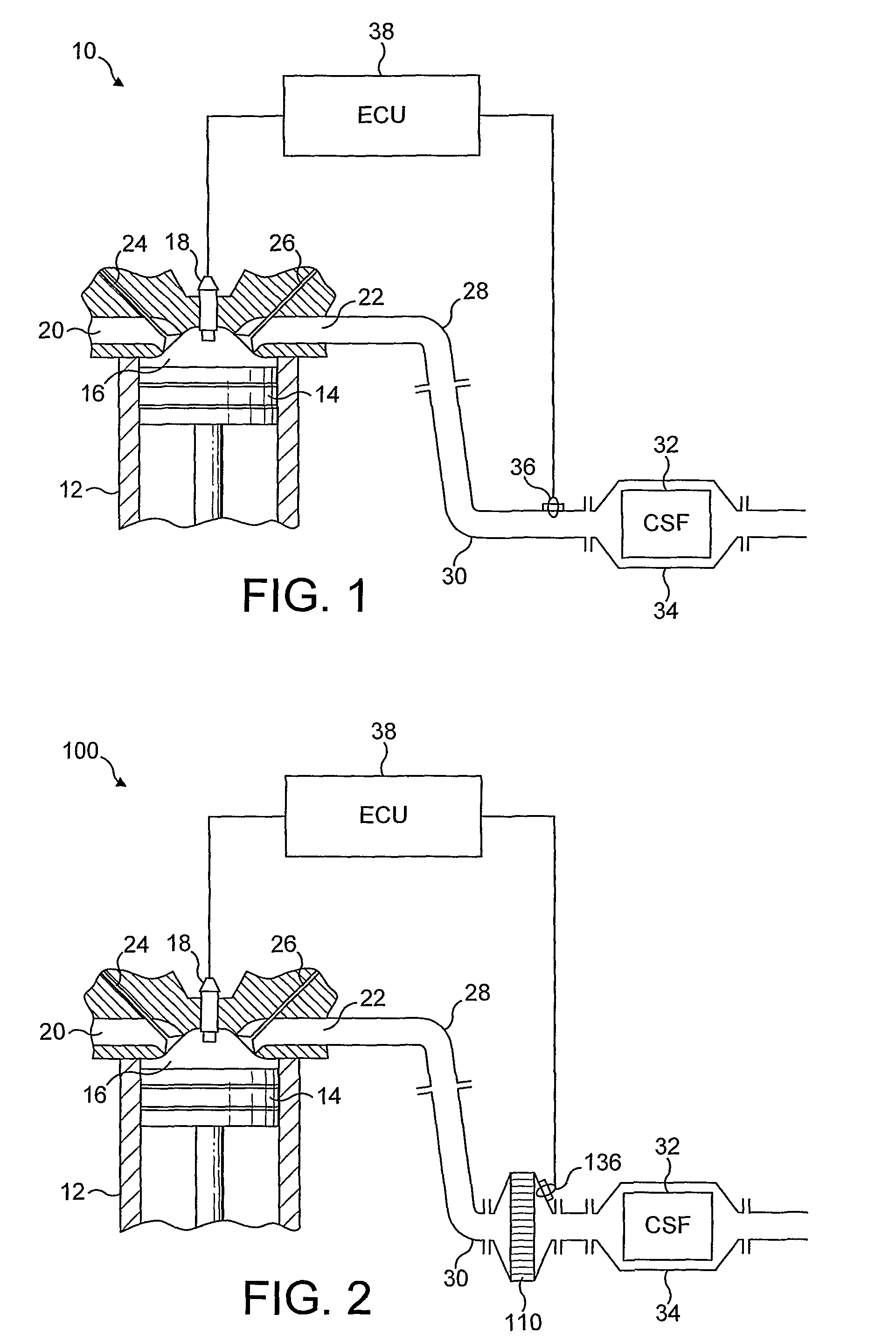
[0041]Referring to FIG. 2, reference numeral 100 refers to a second embodiment according to the invention, wherein like components from FIG. 1 carry the same reference numeral. In FIG. 2, 110 is a short e.g. 2 inch (5 cm) long 5.6 inch (14.2 cm) diameter substrate monolith (or “slice”) e.g. of 400 cpsi ((cells per square inch) 62 cells cm−2) coated with an oxidation catalyst of e.g. Pt / Alumina. Sensor 136 comprises a catalysed thermocouple junction located immediately behind “slice”110, which sensor communicating with ECU 38.

[0042]In use, some HC and / or CO are combusted on the oxidation catalyst 110 and the exotherm generated in the exhaust gas is detected using sensor 136 in addition to the sensor detecting exotherm generated by combusting HC and / or CO on the catalysed sensor itself. A correlation can be made between the detected temperature increase in the exhaust gas and an expected temperature increase in the CSF.


PUM


Abstract

An exhaust system which has a catalysed soot filter (CSF), a control unit, and a catalyzed sensor. The exhaust system, controllable by the control unit, can increase hydrocarbon (HC) and / or carbon monoxide (CO) content in an exhaust gas flowing into the CSF resulting in combustion of the HC and / or CO in the CSF, a temperature increase of the CSF, and combustion of particulate matter collected on the CSF. The catalyzed sensor is disposed between an engine manifold and the CSF, and combusts CO and / or HC in the exhaust gas and inputs the control unit with a datum correlating with an enthalpy of combustion of HC and / or CO in the exhaust gas, thereby controlling the content of the combustible HC and / or CO in the exhaust gas flowing into the CSF. The catalysed sensor is the only catalysed component in the exhaust system disposed between the engine and the CSF.

Description

CROSS-REFERENCE TO RELATED APPLICATIONS[0001]This application is the U.S. National Phase application of PCT International Application No. PCT / GB2007 / 050059, filed Feb. 13, 2007, and claims priority of British Patent Application No. 0603898.8, filed Feb. 28, 2006, both of which are incorporated herein by reference.FIELD OF THE INVENTION[0002]The present invention relates to an exhaust system for a lean burn internal combustion engine comprising a catalysed soot filter (CSF), a control unit, and means, controllable by the control unit, for increasing a content of combustible hydrocarbon (HC) and / or carbon monoxide (CO) in an exhaust gas flowing into the CSF thereby to combust the HC and / or CO in the CSF, to increase the temperature of the CSF and to combust particulate matter (PM) collected thereon.BACKGROUND OF THE INVENTION[0003]It is known to use a CSF to meet legislated exhaust gas emissions for PM, CO and HC in light-duty diesel vehicles (as defined by the relevant legislation). ...

Claims


Application Information

Patent Timeline
Patent Type & Authority Patents(United States)
IPC IPC(8): F01N9/00
CPCF01N3/0253F01N3/035F01N3/106F01N13/008F01N13/009F02D41/029F02D41/1444F01N2340/00F01N2560/00F01N2560/023F02D41/025F02D2200/0804F01N2560/022F01N3/023F01N3/025
Inventor PHILLIPS, PAUL RICHARDTWIGG, MARTYN VINCENT
Owner JOHNSON MATTHEY PLC
Learn More